Liner hanger with sliding sleeve valve

a technology of sliding sleeve valve and liner hanger, which is applied in the direction of drilling casings, drilling pipes, borehole/well accessories, etc., can solve the problems of increased drilling rig time, increased cost, and required equipment changes,

Inactive Publication Date: 2005-12-20
ENVENTURE GLOBAL TECH LLC
View PDF771 Cites 54 Cited by
  • Summary
  • Abstract
  • Description
  • Claims
  • Application Information

AI Technical Summary

Problems solved by technology

Such a large borehole diameter involves increased costs due to heavy casing handling equipment, large drill bits and increased volumes of drilling fluid and drill cuttings.
Moreover, increased drilling rig time is involved due to required cement pumping, cement hardening, required equipment changes due to large variations in hole diameters drilled in the course of the well, and the large volume of cuttings drilled and removed.

Method used


Image

  • Liner hanger with sliding sleeve valve
  • Liner hanger with sliding sleeve valve
  • Liner hanger with sliding sleeve valve

Examples


Embodiment Construction

[0056]A liner hanger assembly having sliding sleeve bypass valve is provided. In several alternative embodiments, the liner hanger assembly provides a method and apparatus for forming or repairing a wellbore casing, a pipeline or a structural support.

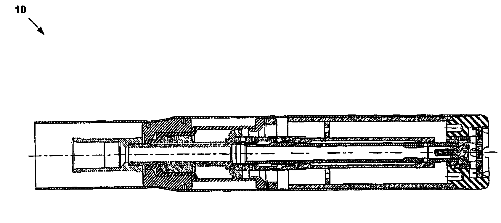
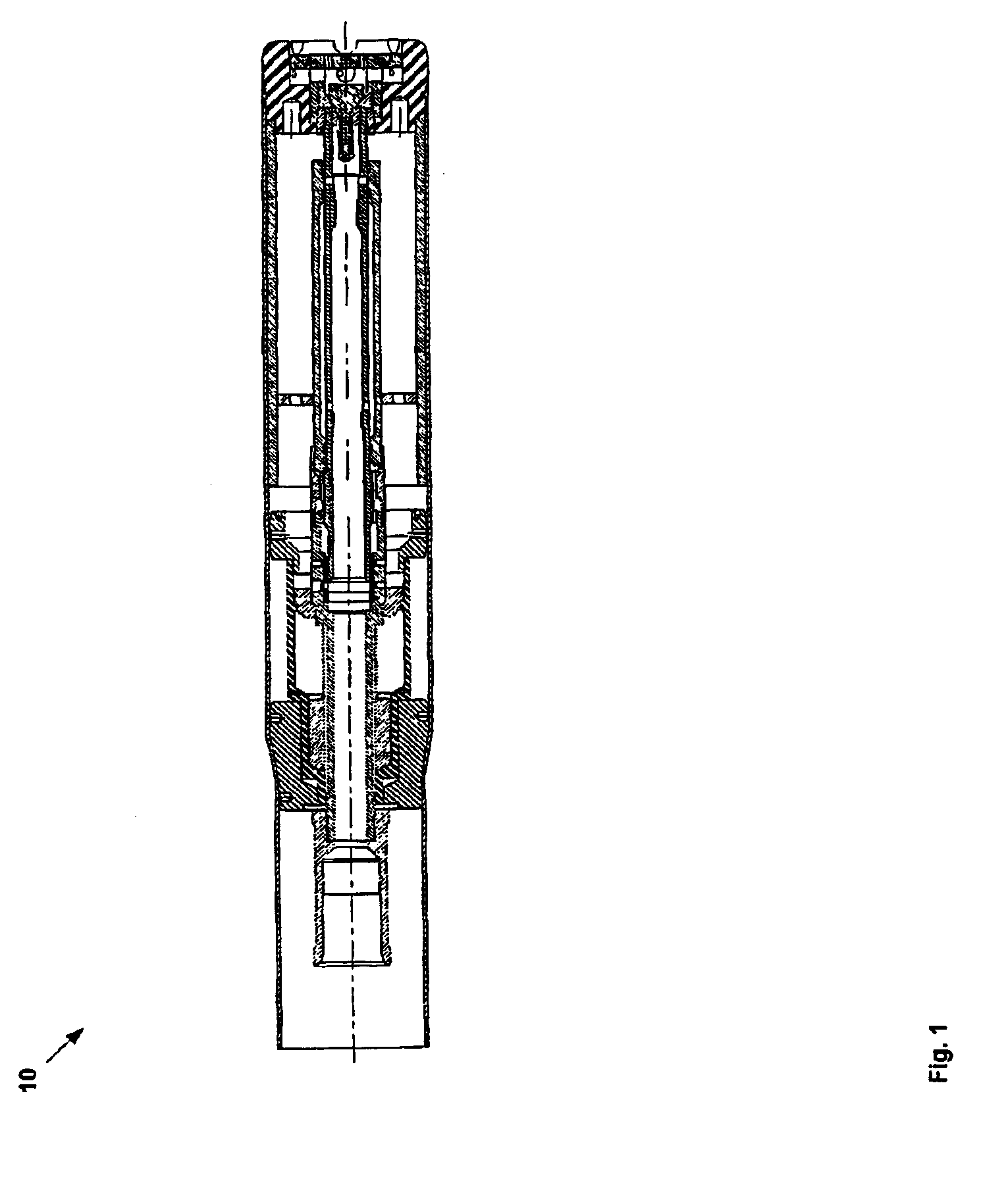
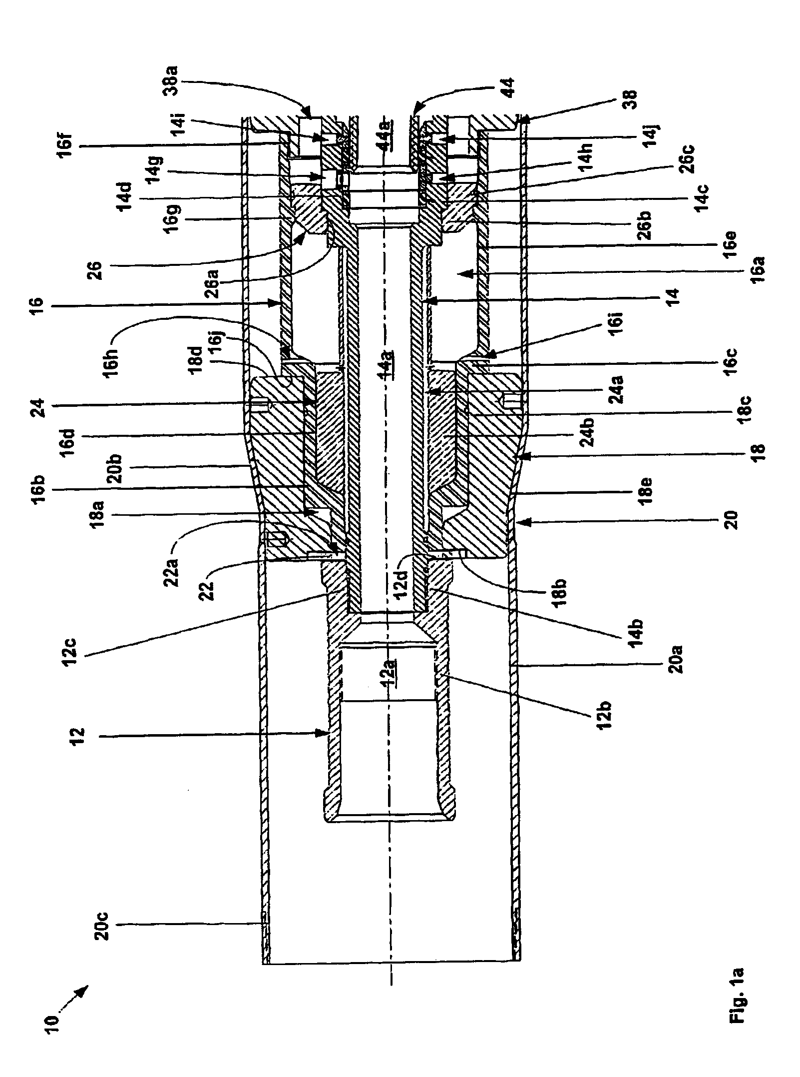
[0057]Referring initially to FIGS. 1, 1a, 1b, and 1c, an embodiment of a liner hanger assembly 10 includes a first tubular support member 12 defining an internal passage 12a that includes a threaded counterbore 12b at one end, and a threaded counterbore 12c at another end. A second tubular support member 14 defining an internal passage 14a includes a first threaded portion 14b at a first end that is coupled to the threaded counterbore 12c of the first tubular support member 12, a stepped flange 14c, a counterbore 14d, a threaded portion 14e, and internal splines 14f at another end. The stepped flange 14c of the second tubular support member 14 further defines radial passages 14g, 14h, 14i, and 14j. A third tubular support member 16 defi...


PUM


Abstract

An apparatus and method for forming or repairing a wellbore casing, a pipeline, or a structural support. An expandable tubular member is radially expanded and plastically deformed by an expansion cone that is displaced by hydraulic pressure. Before or after the radial expansion of the expandable tubular member, a sliding sleeve valve within the apparatus permit a hardenable fluidic sealing material to be injected into an annulus between the expandable tubular member and a preexisting structure.

Description

CROSS REFERENCE TO RELATED APPLICATIONS[0001]This application is a National Phase of the International Application No. PCT / US01 / 28960 filed Sep. 17, 2001, which is based on U.S. application Ser. No. 60 / 233,638, filed on Sep. 18, 2000, the disclosure of which is incorporated herein by reference.[0002]This application is related to the following applications: (1) U.S. patent application Ser. No. 09 / 454,139, filed on Dec. 3, 1999, now U.S. Pat. No. 6,497,289 issued Dec. 24, 2002, (2) U.S. patent application Ser. No. 09 / 510,913, filed on Feb. 23, 2000, (3) U.S. patent application Ser. No. 09 / 502,350, filed on Feb. 10, 2000, now U.S. Pat. No. 6,823,937 issued Nov. 30, 2004, (4) U.S. patent application Ser. No. 09 / 440,338, filed on Nov. 15 1999, now U.S. Pat. No. 6,328,113 issued Dec. 11, 2001, (5) U.S. patent application Ser. No. 09 / 523,468, filed on Mar. 10, 2000, now U.S. Pat. No. 6,640,903 issued Nov. 14, 2003, (6) U.S. patent application Ser. No. 09 / 512,895, filed on Feb. 24, 2000, (...

Claims


Application Information

Patent Timeline
Patent Type & Authority Patents(United States)
IPC IPC(8): E21B33/16E21B34/06E21B34/14E21B43/10
CPCE21B33/16E21B34/063E21B34/14E21B43/105
Inventor BRISCO, DAVID PAULZWALD, JR., EDWIN ARNOLDDAIGLE, CHANNOEL, GREGORYDEAN, WILLIAM J.FILIPPOV, ANDREI GREGORYNIDA, RONALD D.COOK, ROBERT LANCERING, LEVWADDELL, KEVIN K.STEPHENSON, WILLIAM RUSTYGUSEVIK, RUNE T.
Owner ENVENTURE GLOBAL TECH LLC
Why Eureka
Try Eureka