
Stent

a technology of stents and catheters, applied in the field of stents, can solve the problems of considerable loading on the blood vessel, shortening in length to a relatively great degree, etc., and achieve the effect of reducing the length reduction upon expansion

Inactive Publication Date: 2005-12-20
BIOTRONIK MESS UND THERAPIEGERAETE GMBH & CO
View PDF21 Cites 15 Cited by
  • Summary
  • Abstract
  • Description
  • Claims
  • Application Information

AI Technical Summary

Benefits of technology

[0004]Therefore the object of the present invention is to provide a stent of the general kind set forth, which does not suffer from the above-indicated disadvantages or at least suffers therefrom to a lesser degree, and which in particular has a reduced reduction in length upon expansion.

Problems solved by technology

Admittedly, those stents are relatively flexible by virtue of their design configuration with the bar elements extending in a meander configuration in the longitudinal direction of the stent, but they suffer from the disadvantage that they shorten in length to a relatively great degree upon being expanded from the first condition into the second condition.
That is undesirable as in that case on the one hand they experience a change in position in the blood vessel and on the other hand, upon the reduction in length, under some circumstances considerable loadings can be applied to the blood vessel.

Method used


Image

  • Stent
  • Stent
  • Stent

Examples


Embodiment Construction

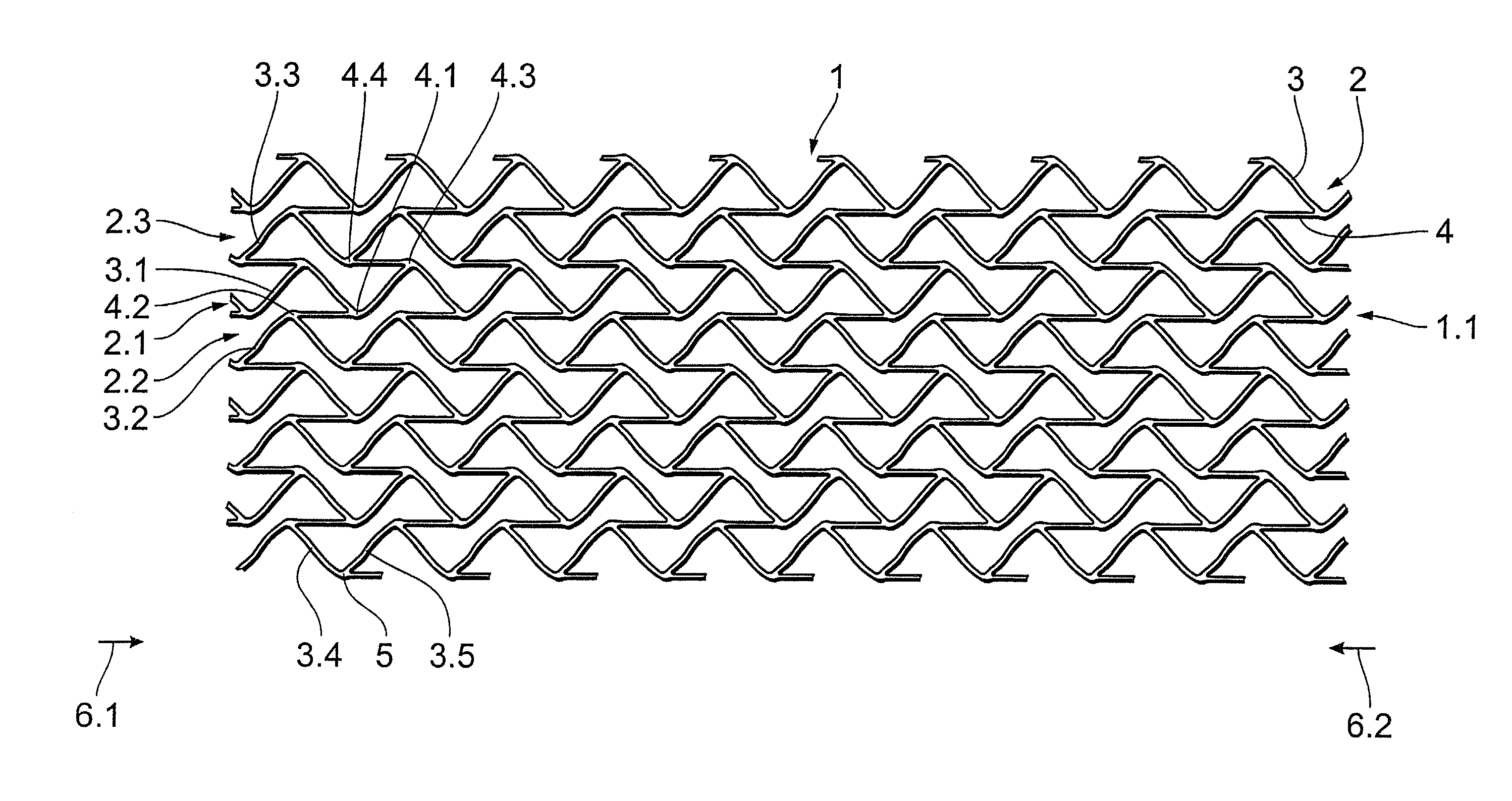
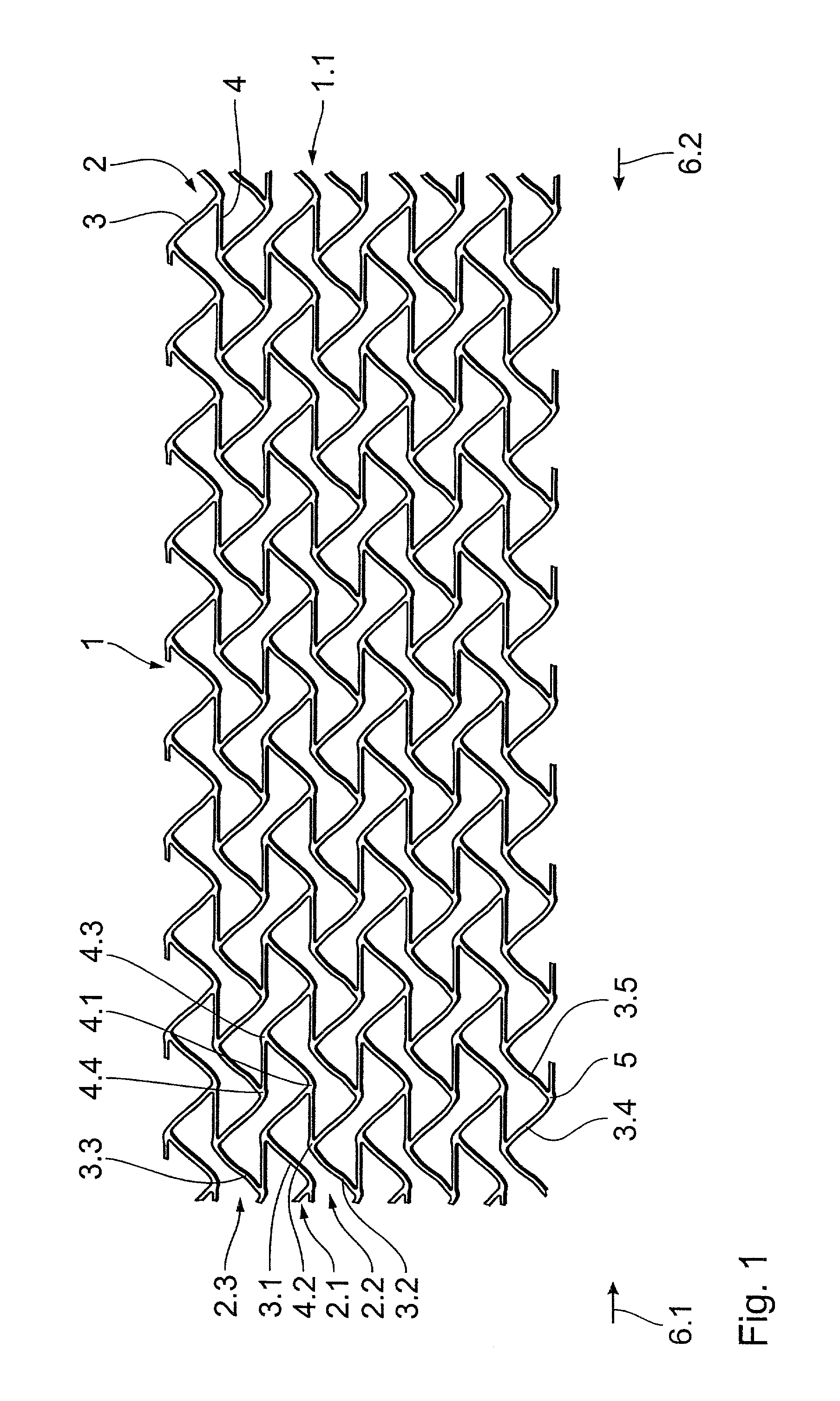
[0025]FIG. 1 is a plan view of the development of the peripheral surface 1 of a preferred embodiment of the stent according to the invention, with support portions 2 formed by bar elements 3 extending in a meander configuration in the longitudinal direction of the stent. Those bar elements 3 are connected together in the peripheral direction of the stent by way of first connecting bars 4.

[0026]The stent has support portion groups 1.1 with a first support portion 2.1 and a second support portion 2.2 which is in adjacent relationship therewith in the peripheral direction, wherein the first engagement points 4.1 engage the first bar elements 3.1 of the first support portions 2.1 and the second engagement points 4.2 of the connecting bars 4 engage the second bar elements 3.2 of the second support portions 2.2. The connecting bars 4 each engage a respective reversal or turning point 5 of the bar element 3.

[0027]The connecting bars 4 extend rectilinearly in the longitudinal direction of t...


PUM


Abstract

A stent, in particular a coronary stent, for expansion from a first condition into an expanded second condition in which it holds a vessel in an expanded state, comprising a tubular body whose peripheral surface (1) is formed by a number of support portions (2) which extend in the longitudinal direction of the stent and which comprise bar elements (3) which are connected by way of connecting bars (4), wherein there is provided a number of support portion groups (1.1) with at least a first support portion (2.1) and a second support portion (2.2, 2.3) in adjacent relationship in the peripheral direction of the stent, whose bar elements (3.1, 3.2, 3.3) extend in a meander configuration in the longitudinal direction of the stent, and wherein the first engagement points (4.1, 4.2) of first connecting bars (4) engage the first support portion (2.1) and the second engagement points (4.2, 4.4) of the first connecting bars (4) engage the second support portion (2.2, 2.3), wherein the first and second engagement points (4.1, 4.3, 4.2, 4.4) of the first connecting bars (4) are spaced from each other in the longitudinal direction of the stent and the first connecting bars (4) are of such a configuration and arrangement that the spacing between the first and second engagement points (4.1, 4.3, 4.2, 4.4) of the first connecting bars (4) in the longitudinal direction of the stent changes upon expansion of the stent to compensate for the reduction in length of the support portions.

Description

[0001]The present invention concerns a stent, in particular a coronary stent, for expansion from a first condition into an expanded second condition in which it holds a vessel in an expanded state, comprising a tubular body whose peripheral surface is formed by a number of support portions which extend in the longitudinal direction of the stent and comprise bar elements which are connected by way of connecting bars. That arrangement has a number of support portion groups with at least a first support portion and a second support portion in adjacent relationship in the peripheral direction of the stent, the bar elements thereof extending in a meander configuration in the longitudinal direction of the stent. In addition the first engagement points of first connecting bars engage the first support portion and the second engagement points of the first connecting bars engage the second support portion.BACKGROUND OF THE ART[0002]A stent is what is known as an intraluminal expansion elemen...

Claims


Application Information

Patent Timeline
IPC IPC(8): A61F2/91A61F2/915A61M25/12A61M25/14
CPCA61F2/91A61F2/915A61F2002/91533A61F2002/9155
Inventor SCHALDACH, DECEASED, MAXSCHALDACH, JR., LEGAL REPRESENTATIVE, MAXLOOTZ, DANIELKOOP, KARSTENKRANZ, CURT
Owner BIOTRONIK MESS UND THERAPIEGERAETE GMBH & CO
Learn More