Auxiliary power supply unit and portable electronic system

a technology electronic system, which is applied in the field of auxiliary power supply, can solve the problems of heat generation of batteries, worse explosion, and leakage of liquid, and achieve the effect of reducing the fluctuation of power supply voltage of portable electronic devices and improving the consumption efficiency of batteries loaded

Inactive Publication Date: 2005-12-20
RICOH IMAGING COMPANY
View PDF15 Cites 11 Cited by
  • Summary
  • Abstract
  • Description
  • Claims
  • Application Information

AI Technical Summary

Benefits of technology

[0008]An object of the present invention is to provide an auxiliary power supply unit and a portable electronic system which can restrain power supply voltage fluctuation of a portable electronic device and which can improve the consuming efficiency of a battery loaded in the portable electronic device.

Problems solved by technology

If battery continues to be used after the battery voltage drops below the final voltage, the battery may produce heat, which in turn may leak liquid, or worse explode, under some conditions.
If battery leaks or explodes, a device in which the battery is loaded may malfunction or may be damaged.
When the portable electronic device operates at a low temperature or when the portable electronic device is performing an operation requiring a large current sporadically, the internal resistance of the battery appears to increase, which may cause a power-supply-voltage detecting circuit provided in the device to mistakenly determine that the battery voltage has reached the final voltage.
In this case, the user is erroneously informed that the battery is nearly exhausted, and therefore he or she replaces the battery with a new one.
Consequently, the energy of the battery is not used up sufficiently.
However, all of these proposals cause the portable electronic device to be increased in size, thereby increasing weight and increasing the cost of production, which are undesirable.
In addition, such proposals can be wasteful since, in some cases, the final voltage is hardly ever mistakenly detected under some conditions.

Method used


Image

  • Auxiliary power supply unit and portable electronic system
  • Auxiliary power supply unit and portable electronic system
  • Auxiliary power supply unit and portable electronic system

Examples


Embodiment Construction

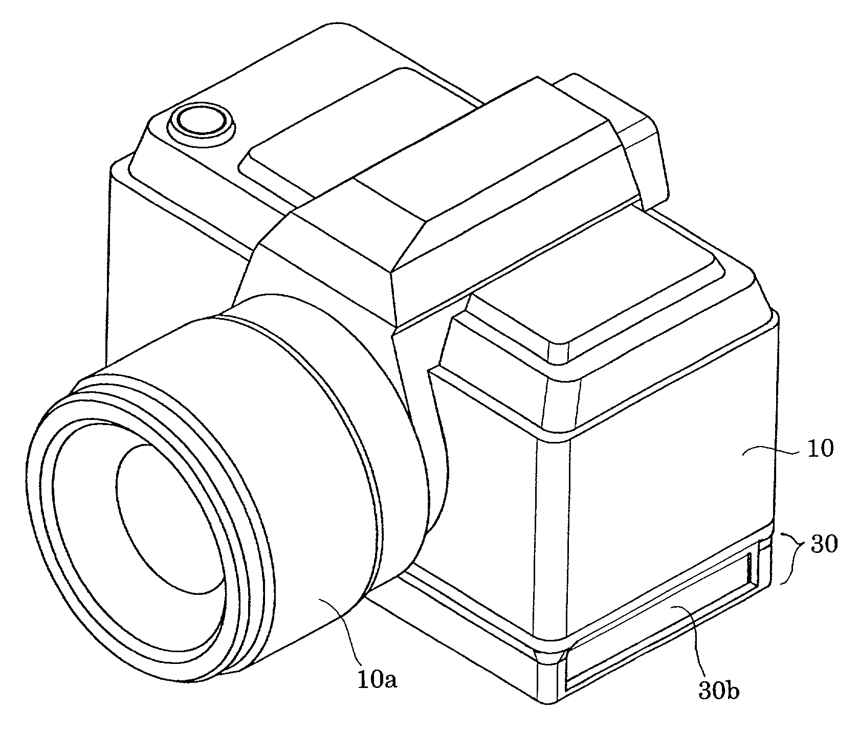
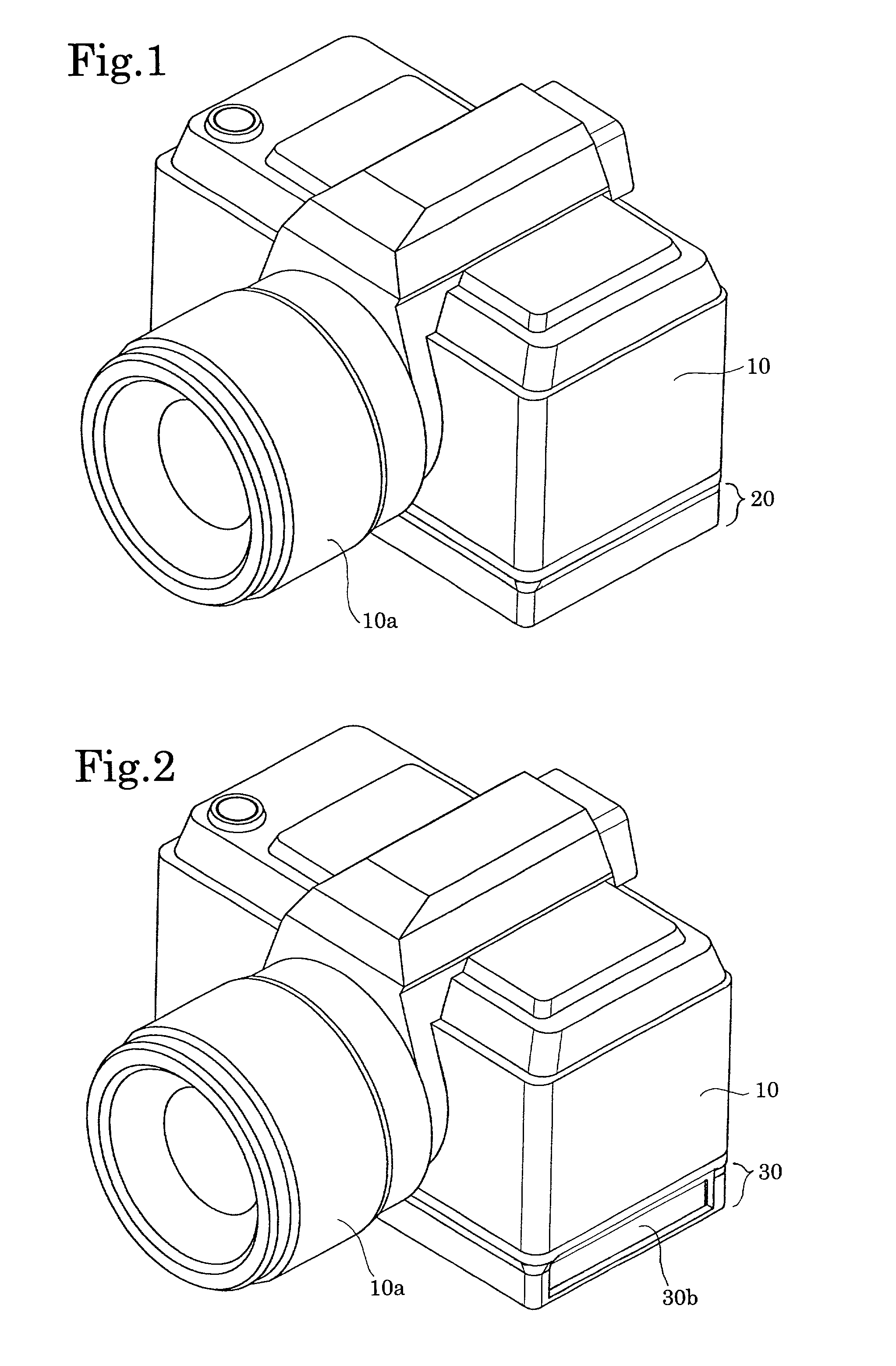
[0039]The overall structure of a digital camera system (portable electronic system) to which the present invention is applied will be hereinafter discussed with reference to FIGS. 1 through 4. The digital camera system is composed of a camera body (portable electronic device / digital camera) 10 to which a photographing lens 10a is fixed, and camera accessories which are mounted to the camera body 10 when in use. The camera accessories include an auxiliary power supply unit 20 shown in FIG. 4 and a printer unit 30 shown in FIG. 5. FIG. 1 shows a state of the digital camera system in which the auxiliary power supply unit 20 is mounted to the bottom of the camera body 10, while FIG. 2 shows another state of the digital camera system in which the printer unit 30 is mounted to the bottom of the camera body 10.

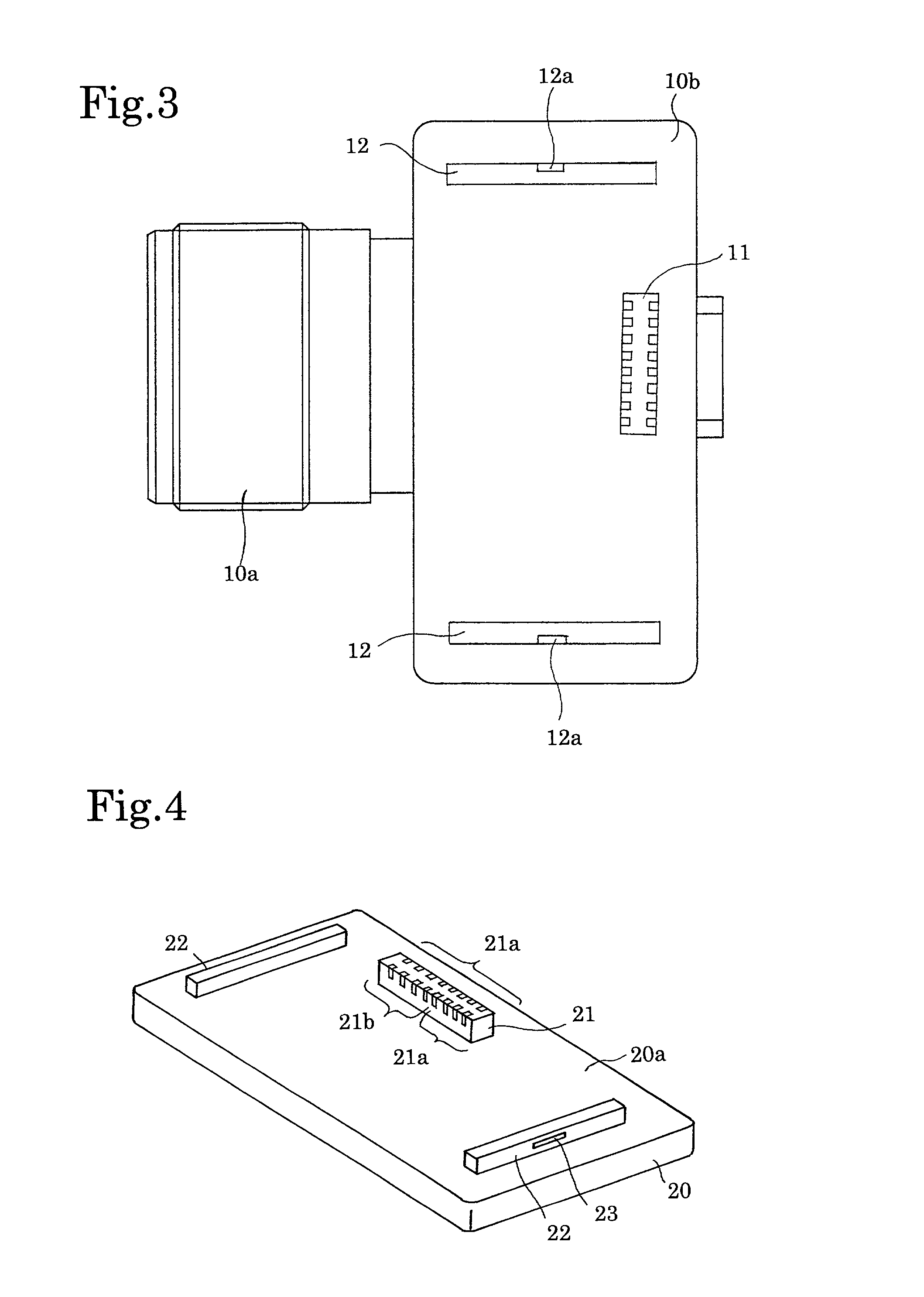
[0040]The camera body 10 is provided on a bottom surface 10b thereof with an I / F socket (I / F connector) 11 and a pair of locking / locating slots 12 (see FIG. 3). The pair of locking / l...


PUM

PropertyMeasurementUnit
temperatureaaaaaaaaaa
internal resistanceaaaaaaaaaa
voltageaaaaaaaaaa

Abstract

An auxiliary power supply unit which is mountable to a portable electronic device having a battery, includes at least one capacitor, and an I/F connector which is connectable to an I/F connector of the portable electronic device, the I/F connector of the portable electronic device including power terminals connected to the battery. The I/F connector of the auxiliary power supply unit includes power terminals connected to the at least one capacitor, wherein the at least one capacitor is connected in parallel to the battery when the auxiliary power supply unit is mounted to the portable electronic device via the power terminals of the I/F connectors.

Description

BACKGROUND OF THE INVENTION[0001]1. Field of the Invention[0002]The present invention relates to an auxiliary power supply unit for a portable electronic device, and also relates to a portable electronic system which is composed of a portable electronic device, such as a digital camera, and one or more associated accessories.[0003]2. Description of the Related Art[0004]Various types of batteries are available on the market; each type generally has a factory-recommended final voltage which guarantees the safety of the battery. If battery continues to be used after the battery voltage drops below the final voltage, the battery may produce heat, which in turn may leak liquid, or worse explode, under some conditions. If battery leaks or explodes, a device in which the battery is loaded may malfunction or may be damaged.[0005]To prevent such problems from occurring, in conventional portable electronic devices which use a battery as a power supply, the battery voltage is regularly checked...

Claims


Application Information

Patent Timeline
Patent Type & Authority Patents(United States)
IPC IPC(8): H01M10/44H02J7/00H04N5/225
CPCH04N5/2251H04N23/50H04N23/60
Inventor HANADA, YUJIKAKIUCHI, SHINICHI
Owner RICOH IMAGING COMPANY
Why Eureka
Try Eureka