Power control with space time transmit diversity

a power control and space time technology, applied in power management, wireless communication, electronic wave modulation, etc., can solve the problems of significant fading or variation in the strength of received signals, failure to teach such a transmit diversity scheme for a wcdma communication system, and failure of otd and tstd systems to exploit the extra path diversity that is possible in open loop systems, etc., to achieve the effect of improving closed-loop power control

Inactive Publication Date: 2005-12-20
INTEL CORP
View PDF23 Cites 84 Cited by
  • Summary
  • Abstract
  • Description
  • Claims
  • Application Information

AI Technical Summary

Benefits of technology

[0011]The present invention improves closed-loop power control by providing at least 2L diversity over time and space. No additional transmit power or bandwidth is required. Power is balanced across multiple antennas.

Problems solved by technology

These different data signals arrive at the receiver via multiple paths due to ground clutter and unpredictable signal reflection.
Additive effects of these multiple data signals at the receiver may result in significant fading or variation in received signal strength.
Tarokh et al. and Alamouti, however, fail to teach such a transmit diversity scheme for a WCDMA communication system.
Both OTD and TSTD systems, however, fail to exploit the extra path diversity that is possible for open loop systems.
The OTD and TSTD methods, therefore, are limited to a path diversity of L. This path diversity limitation fails to exploit the extra path diversity that is possible for open loop systems as will be explained in detail.
Previous methods of diversity have also failed to exploit closed-loop power control between a mobile communication system and a remote base station.
Thus, the power control system of FIG. 7 fails to exploit advantages of closed-loop power control with path diversity.
The TSTD method, however, is limited to a path diversity of L. Moreover, two time slots are required for each transmit power adjustment from time tm1 to time ts.
Thus, the TSTD system has an additional disadvantage of imprecise power control due to increased time between received power measurement and transmit power adjustment.

Method used


Image

  • Power control with space time transmit diversity
  • Power control with space time transmit diversity
  • Power control with space time transmit diversity

Examples


Embodiment Construction

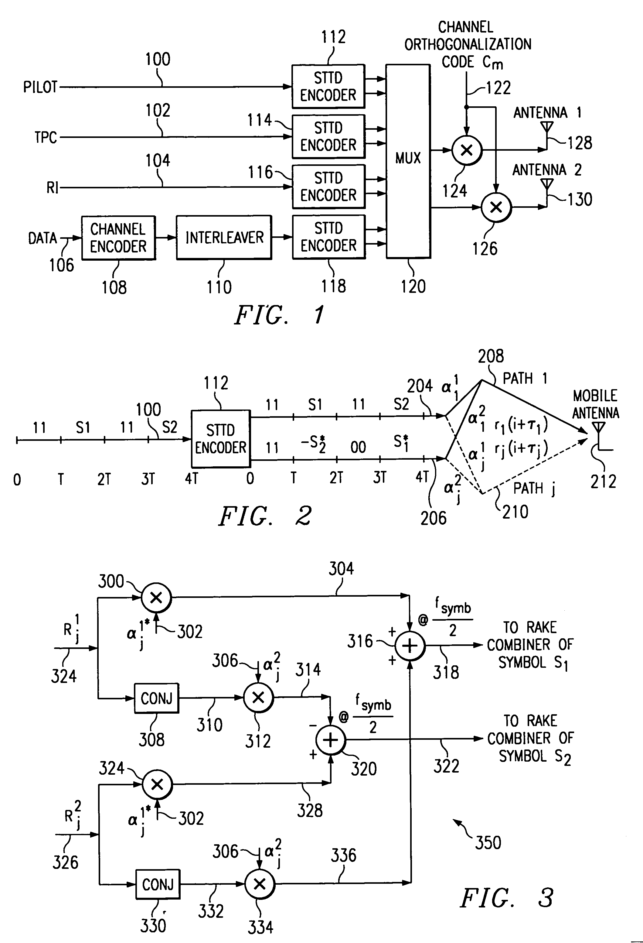
[0028]Referring to FIG. 1, there is a simplified block diagram of a typical transmitter using Space Time Transit Diversity (STTD) of the present invention. The transmitter circuit receives pilot symbols, TPC symbols, RI symbols and data symbols on leads 100, 102, 104 and 106, respectively. Each of the symbols is encoded by a respective STTD encoder as will be explained in detail. Each STTD encoder produces two output signals that are applied to multiplex circuit 120. The multiplex circuit 120 produces each encoded symbol in a respective symbol time of a frame. Thus, a serial sequence of symbols in each frame is simultaneously applied to each respective multiplier circuit 124 and 126. A channel orthogonal code Cm is multiplied by each symbol to provide a unique signal for a designated receiver. The STTD encoded frames are then applied to antennas 128 and 130 for transmission.

[0029]Turning now to FIG. 2, there is a block diagram showing signal flow in an STTD encoder of the present in...


PUM


Abstract

A circuit is designed with a measurement circuit (432). The measurement circuit is coupled to receive a first input signal (903) from a first antenna (128) of a transmitter and coupled to receive a second input signal (913) from a second antenna (130) of the transmitter. Each of the first and second signals is transmitted at a first time. The measurement circuit produces an output signal corresponding to a magnitude of the first and second signals. A control circuit (430) is coupled to receive the output signal and a reference signal. The control circuit is arranged to produce a control signal at a second time in response to a comparison of the output signal and the reference signal.

Description

FIELD OF THE INVENTION[0001]This invention relates to wideband code division multiple access (WCDMA) for a communication system and more particularly to power control with space time transmit diversity for WCDMA signals.BACKGROUND OF THE INVENTION[0002]Present code division multiple access (CDMA) systems are characterized by simultaneous transmission of different data signals over a common channel by assigning each signal a unique code. This unique code is matched with a code of a selected receiver to determine the proper recipient of a data signal. These different data signals arrive at the receiver via multiple paths due to ground clutter and unpredictable signal reflection. Additive effects of these multiple data signals at the receiver may result in significant fading or variation in received signal strength. In general, this fading due to multiple data paths may be diminished by spreading the transmitted energy over a wide bandwidth. This wide bandwidth results in greatly reduc...

Claims


Application Information

Patent Timeline
Patent Type & Authority Patents(United States)
IPC IPC(8): H04B1/00H04B1/02H04B1/707H04B7/005H04B7/185H04B7/216
CPCH04B7/0669H04W52/42H04B1/712H04B2201/70707H04W52/08H04W52/241H04W52/245
Inventor HOSUR, SRINATHDABAK, ANAND G.
Owner INTEL CORP
Why Eureka
Try Eureka