
Drum assembly having helical gear and spur gear spaced therebetween for use in printer

Inactive Publication Date: 2005-12-20
PARK&OPC
View PDF3 Cites 5 Cited by
  • Summary
  • Abstract
  • Description
  • Claims
  • Application Information

AI Technical Summary

Benefits of technology

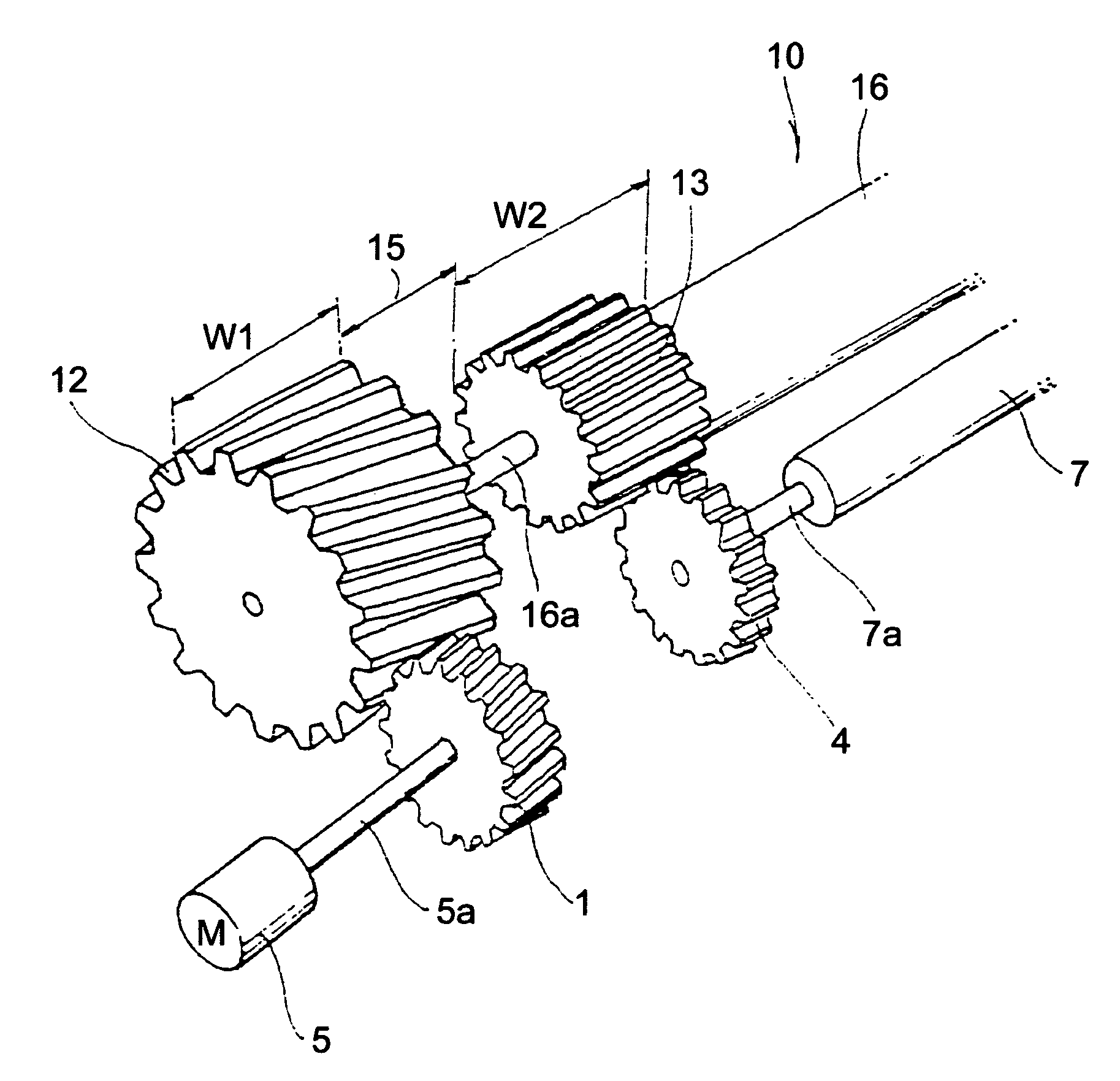
[0015]It is a principal object of the present invention to provide a photo-sensitive drum assembly for use in an image forming apparatus, wherein the interference between the helical gear and the driving force transmitting gears of other parts which is caused by the integral formation of the helical gear and the spur gear is prevented by making a gap between the helical gear and the spur gear which are mounted to a side of the photo-sensitive drum for transmitting the driving force.
[0016]It is another object of the present invention to provide a photo-sensitive drum assembly for use in an image forming apparatus, wherein the general cutting work can be used for production and the production cost by the injection molding is reduced.
[0017]According to an aspect of the present invention, there is provided a photo-sensitive drum assembly for use in an image forming apparatus, comprising a helical gear for receiving a rotational driving force by engaging with a driving gear of a driving motor; a 2nd spur gear attached to a lateral side of a shaft for transmitting the rotational driving force to a transfer roller; and a 1st spur gear, engaging with the 2nd spur gear, deployed coaxially in parallel to a lateral side in a longitudinal direction, wherein the helical gear is installed next to the 1st spur gear with a gap to thereby prevent an interference between the helical gear and the 2nd spur gear of the transfer roller moving in an axial direction.

Problems solved by technology

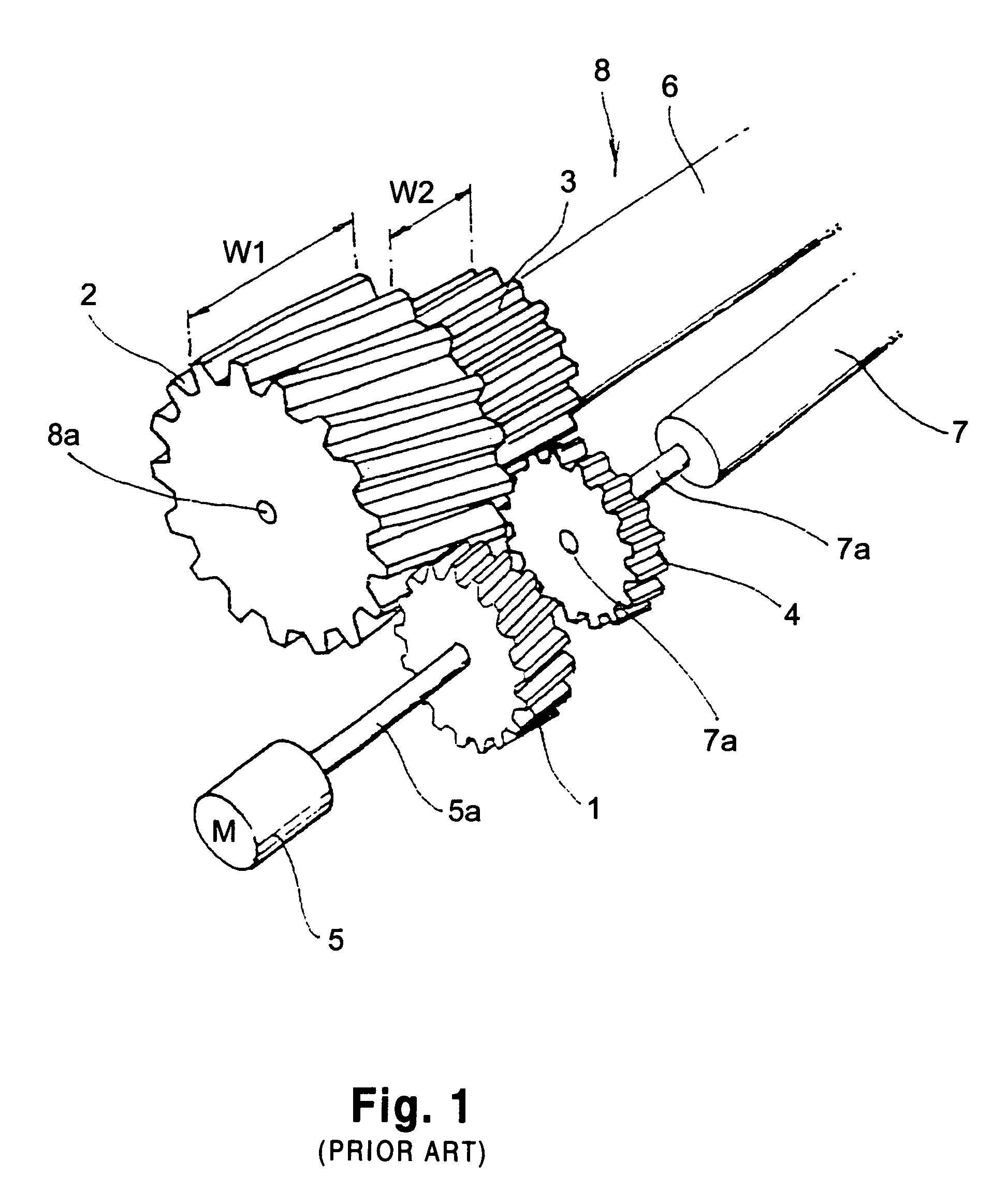
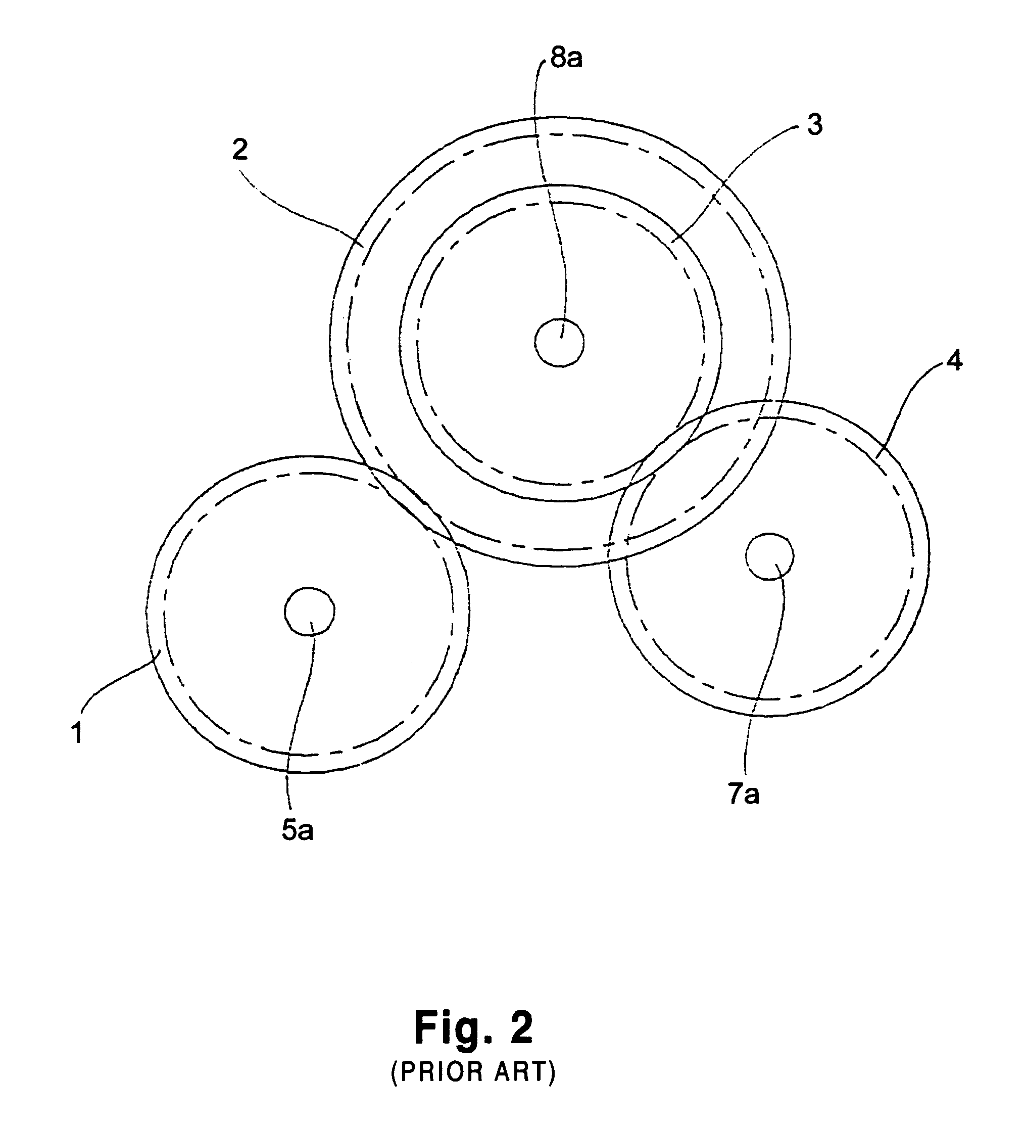
This misalignment is a problem that undesirable image is transferred to the transfer paper which passes between the photo-sensitive drum 8 and the transfer roller 7.
If the width of the 2nd spur gear is narrow, the area wherein the 1st spur engages with the 2nd spur gear is small and there is a possibility that insufficient driving force is transmitted to the transfer roller 7 by the narrowed 2nd spur gear.
Moreover, polycarbonate has been used in the conventional production of the unified body of the helical gear 2 and the 1st spur gear 3 by using the injection molding, but there is still a problem that the production cost is rather high because the polycarbonate is expensive.

Method used


Image

  • Drum assembly having helical gear and spur gear spaced therebetween for use in printer
  • Drum assembly having helical gear and spur gear spaced therebetween for use in printer
  • Drum assembly having helical gear and spur gear spaced therebetween for use in printer

Examples


Embodiment Construction

[0025]Hereinafter, preferred embodiments of the present invention will be explained with reference to the accompanying drawings, wherein like numerals refer to like parts throughout.

[0026]FIG. 4 and FIG. 5 are a perspective view and a front view, respectively of a photo-sensitive drum assembly 10, in accordance with a preferred embodiment of the present invention.

[0027]The photo-sensitive drum assembly 10 of the present invention includes a driving motor 5, a driving gear 1 receiving a rotational driving force from the driving motor 5 by being attached to a driving shaft 5a of the driving motor 5, a helical gear 12 which accepts the rotational driving force originated from the driving motor 5 by engaging with the driving motor 5, an extended driving shaft 16a extending from the central shaft of the helical gear 12 for transmitting the rotational driving force of the helical gear 12, a photo-sensitive drum 16, having a cylindrical body and for forming the toner image in conformity wi...


PUM


Abstract

The present invention relates to a photo-sensitive drum assembly for use in an ink-jet printer or a laser printer.According to the present invention, there is provided a photo-sensitive drum assembly capable of preventing a helical gear from interrupting a first spur gear while engages with a second spur gear, by placing a gap between the helical gear and the first spur gear, in case that the helical gear which accept the rotational driving force and the first spur gear which transmits the rotational driving force are positioned on a common axis.

Description

FIELD OF THE INVENTION[0001]The present invention relates to a photo-sensitive drum assembly for forming an image in an image forming apparatus, and more particularly, to a photo-sensitive drum assembly for use in an image forming apparatus not to make a helical gear interrupt a spur gear, which engages with another spur gear, by making a gap between two gears when the helical gear which receives the rotational driving force and the spur gear which transmits the rotational driving force stand parallel are coaxially aligned as a unit.DESCRIPTION OF THE PRIOR ART[0002]A laser printer, a digital copying machine, an electro-photographic copying machine and a facsimile are generally known as image forming apparatus. These image forming apparatuses form a toner image on a photo-sensitive drum through the processes such as electric charging, light exposure and developing, transfer the toner image onto a record material such as transfer paper, and remove the remaining toner of the photo-sen...

Claims


Application Information

Patent Timeline
IPC IPC(8): G03G15/00G03G15/02
CPCG03G15/757G03G15/02
Inventor CHUNG, INHOHAN, SEUNGYUBKIM, MINCHUL
Owner PARK&OPC
Learn More