
Combined feature dimensional parameter analysis

a technology of dimensional parameter analysis and combined features, which is applied in the direction of analogue processes, instruments, and specific applications, which can solve the problems of inability to accurately assess the effects of computer simulations with respect to feature relating tolerances, inability to accurately evaluate the effect of computer simulations on the inspection data of manufactured articles and varied feature data in simulations, and inability to achieve automatic evaluation

Active Publication Date: 2005-12-20
THE BOEING CO
View PDF5 Cites 16 Cited by
  • Summary
  • Abstract
  • Description
  • Claims
  • Application Information

AI Technical Summary

Problems solved by technology

However, the manufacturing industry does not have an efficient or effective way of determining whether or not the requirements are achieved.
Furthermore, there is no means for accurately assessing the effects of computer simulations with respect to feature relating tolerances.
Inspection data of manufactured articles and varied feature data in simulations are not currently evaluated in an automated and correct manner to determine whether or not combined feature parameters such as hole size and location are acceptable to the applied feature relating tolerances.
Evaluation of manufactured or simulated hole size, form, orientation, and location are all completed separately, and confidence in the accuracy of each evaluation is low.
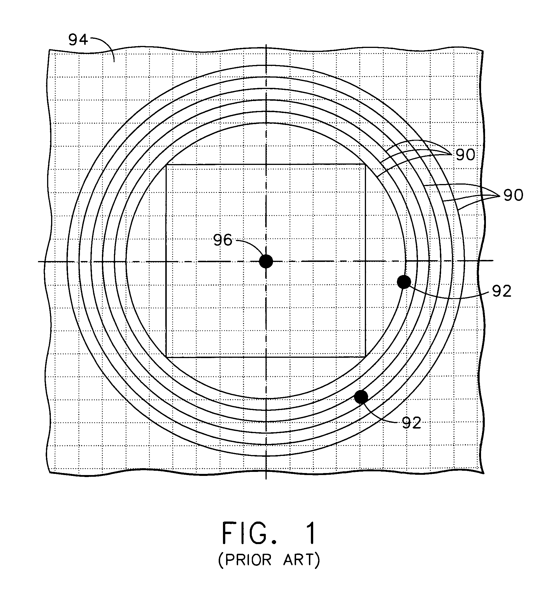
A problem with this method however, is that it is time consuming because it is not automated, nor is this method used with an automated process.
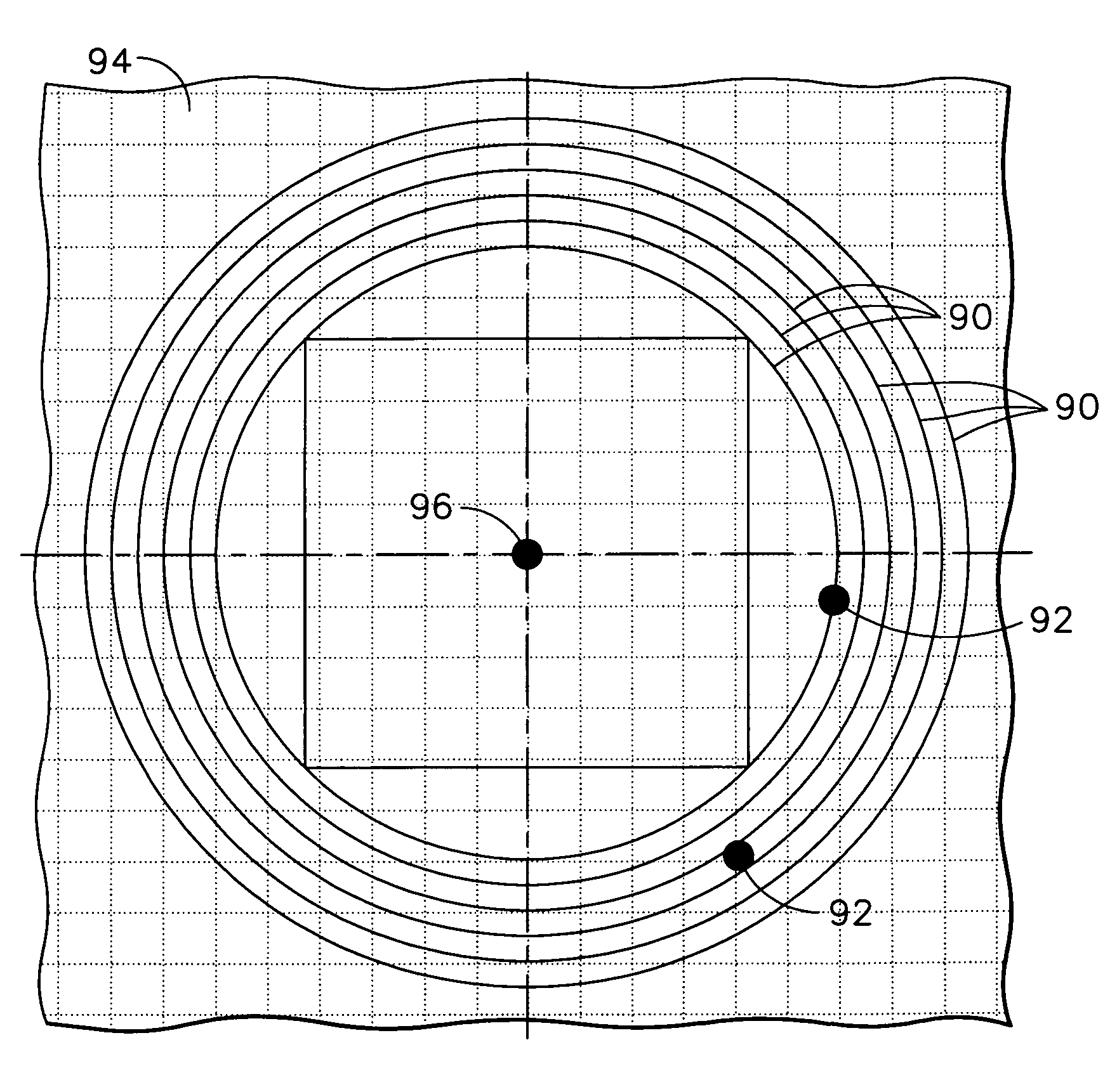
Another problem is the difficulty of best fitting the concentric circles 90 into a position that encompasses all the hole positions 92 within the applicable concentric circle.
However, using approximations reduces accuracy, and using multiple iterations causes excessive analysis time.
Such a process may introduce error, is inefficient, and requires advanced software skills for completion.

Method used


Image

  • Combined feature dimensional parameter analysis
  • Combined feature dimensional parameter analysis
  • Combined feature dimensional parameter analysis

Examples


Embodiment Construction

[0034]The following detailed description is of the best currently contemplated modes of carrying out the invention. The description is not to be taken in a limiting sense, but is made merely for the purpose of illustrating the general principles of the invention, since the scope of the invention is best defined by the appended claims. References to manufactured features may equally refer to features generated in a computer simulation or features produced in fabrication processes.

[0035]The present invention provides a method for determining the size and location of manufactured features on an object, determining the translation of a pattern of features, determining tolerances consumed, and determining remaining feature tolerances. Such method may be, but not limited to, hand-implemented or implemented by a computer program. By determining remaining feature tolerances for features such as holes during or shortly after a manufacturing process, it is possible to determine how the featur...


PUM


Abstract

A computerized method is disclosed for determining the size and location effects of simulated or manufactured features on an object, determining the transformation of a pattern of features, determining usable feature size within a pattern of features, and determining the remaining feature tolerances. The simulated or manufactured position of a pattern of features is used to determine how to translate a tolerance zone framework. Positional errors and remaining feature tolerances are determined relative to the translated design framework.

Description

BACKGROUND OF THE INVENTION[0001]The present invention generally relates to the production of articles of manufacture in a computer simulation or in the real world, and more particularly, to a method for accurately evaluating pattern compliance for a simulated or manufactured article.[0002]American, Canadian, German, and International Organization for Standardization (ISO) standards define methods for specifying multiple levels of feature related tolerances. However, the manufacturing industry does not have an efficient or effective way of determining whether or not the requirements are achieved. Furthermore, there is no means for accurately assessing the effects of computer simulations with respect to feature relating tolerances. Inspection data of manufactured articles and varied feature data in simulations are not currently evaluated in an automated and correct manner to determine whether or not combined feature parameters such as hole size and location are acceptable to the appl...

Claims


Application Information

Patent Timeline
Patent Type & Authority Patents(United States)
IPC IPC(8): G01B15/00G06K9/00
CPCG06T7/0006G06T7/0046G06T2207/30164G06T7/75
Inventor WILSON, BRUCE A.
Owner THE BOEING CO
Learn More