Tilt indicator for firearms

a tilt indicator and firearm technology, applied in the field of firearm control and aiming, can solve the problems of insufficient unaided aiming of firearms, source of inaccuracy, and become so clos

Inactive Publication Date: 2005-12-27
LONG SHOT PROD
View PDF27 Cites 93 Cited by
  • Summary
  • Abstract
  • Description
  • Claims
  • Application Information

AI Technical Summary

Benefits of technology

[0020]Various advantages are achieved by a level indicating system of this invention that provides information regarding whether the firearm is level in a manner which is absorbed by the shooter without interfering with his primary concentration on the target. More specifically, a tilt indicator of the present invention provides a shooter with information which he absorbs using his secondary concentration. In this manner, the tilt of the firearm is relegated to the same concentration area as variables such as sway or balance, breathing, etc., and the shooter can therefore maintain his conscious and primary concentration on the target.
[0023]One specific embodiment of the level indicating system includes a pendulum-type element having a single pivot access, a weight to keep the pendulum suspended and a series of apertures in the pendulum whereby the pendulum acts as a mask for a set of light emitting / light receiving elements. The pendulum can be damped using magnets or spring-like elements so effects of quick movements of the firearm, including recoil, do not adversely affect the tilt sensor system. Still further, stops can be used to further protect the pendulum from undue movement. One form of the embodiment includes infrared detectors and infrared LED emitters. Each emitter is spaced from its corresponding detector with a plumb line located between them.
[0027]Other forms of tilt sensors can be used, including a rolling electrically conductive element, such as a ball. The ball can be used in conjunction with a printed circuit board which defines the exact contacts which are connected by the ball as it rolls along a curved track. One set of contacts indicates level while other contact sets indicate tilted conditions. This is a simple system in which recoil effects are minimized.
[0029]The ball can also be located on a track defined in the circuit board. When the printed circuit board is cut, it is cut so that traces on either side of the circuit board are opposite to each other. When the ball lines up and connects the circuit board traces on either side of the circuit board and across the edge of the board, the circuit is completed. Plating can also enhance the height and shape of the edge of the traces as they appear at the cut edge of the circuit board. This enhancement makes it easier for the ball to contact both electrical traces. Since the ball is spherical and not flat, there is a slight rise in the edge of the traces in order to ensure a complete circuit when the traces contact across the arc of the ball.

Problems solved by technology

Modern competitions have become so close that unaided aiming of a firearm may be insufficient.
Side to side tilt of the firearm is one significant source of inaccuracy.
A hunter is subjected to even more disorienting influences, including the elements (heat, cold, wind, rain, etc.) and rough and uneven terrain.
In addition, hunters may spend hours of hiking through rough and uneven terrain before firing a shot.
Scope builders are challenged to provide a clear and bright image to the eye even at high magnifications.
There is more light loss in the scope as magnification increases which results in a dimmer view of the target.
While accuracy of such larger scopes has increased, they have created problems.
At first blush this seems to be only a problem of mounting the scope.
Practically, however, as the scope is mounted higher and higher from the central bore of the firearm, the sighting system becomes more sensitive to inaccuracies due to errors in repeatability.
Furthermore, in target shooting, competitions have become so close that anything that detracts from the shooter's accuracy can be extremely detrimental.
Stance, instability, physical fatigue, mental fatigue, eye strain and eye fatigue can adversely affect the marksman.
Anything that interferes with the shooter's single primary concentration on the target may be detrimental to his accuracy.
Thus, these designs are not as successful as possible.
Distractions to this concentration such as moving the eye to a bubble level either inside the scope or out of the shooter's field of vision are extremely undesirable and cannot be done simultaneously with sighting the target.
As discussed above, these distractions take the shooter's primary concentration away from the target and thus are undesirable.
However, since these prior sighting units do not recognize that there is a difference between primary concentration and secondary concentration, these sighting units actually detract from the shooter's primary concentration when providing additional information because this additional information is presented in such a manner as to require the shooter to focus his primary concentration on that additional information.
For example, these studies have thus found that cellular telephone use by an automobile driver can be dangerous because the person's primary concentration is not fully focused on his driving, and an accident can occur in the time it takes to shift his concentration from a conversation on the cellular telephone back to his driving.
For this reason, any level indicator that requires the user to align two elements will require the user to change the focus of his primary concentration, no matter where the level indicating elements are located, thereby creating the above-discussed problems and disadvantages.
While scope type sighting systems have been discussed, it is noted that other sighting systems, such as iron sights, also are subject to the above-discussed leveling problems.

Method used


Image

  • Tilt indicator for firearms
  • Tilt indicator for firearms
  • Tilt indicator for firearms

Examples


embodiment

Accelerometer Embodiment

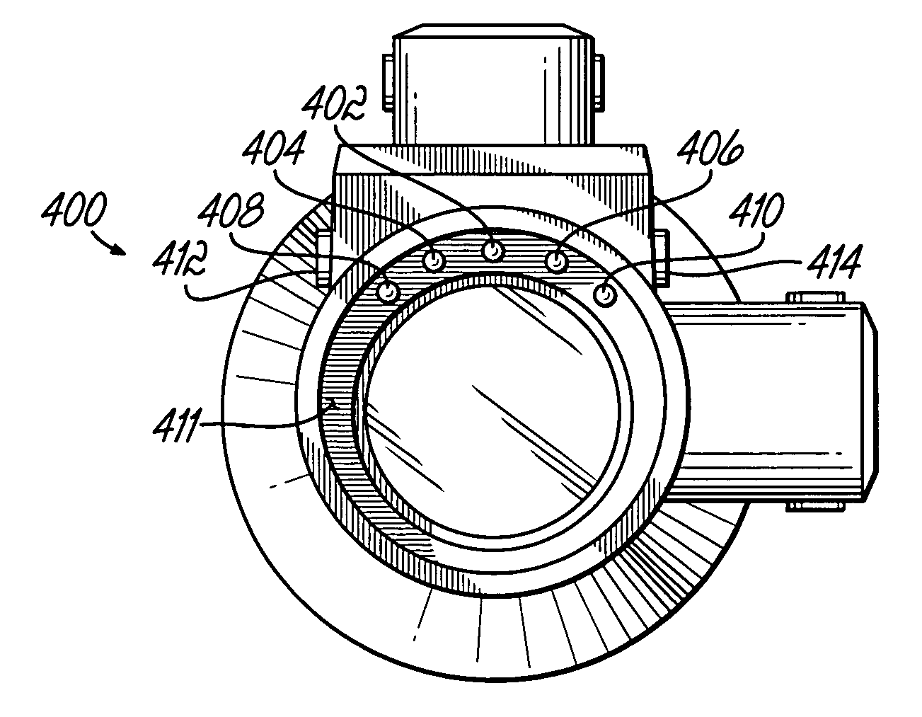
[0120]Referring to FIGS. 28–31, another embodiment interfaces an accelerometer 512 with a controller 514 and signal indicators 402–410 to unobtrusively communicate tilt information to a user of a scope 600 or other sighting device. Generally, the ocular housing of the tilt indicator 400 illustrated in FIG. 29 employs the accelerometer 512 and other tilt sensing circuitry to convey orientation information to the user via at least one signal indicator. As shown in FIG. 29, the peripheral positioning of the signal indicator(s) 402–410 ensures they do not obstruct visual target acquisition when removably attached to a rifle scope 600, as shown in FIG. 28. As may be appreciated, the battery operated tilt indicator 400 is configured to mount onto a scope housing 600 of FIG. 28 with the signal indicators 402–410 (FIG. 29) recessed on an annular ring 411 and oriented in any suitable fashion. Tilt indicator 400 is preferably positioned behind all optical elements or o...


PUM


Abstract

A tilt indicator for use on a firearm includes a signal to indicate if the firearm is level or out of level. The signal is located to be viewed by a user via the user's peripheral vision and his secondary concentration so the user can maintain his primary concentration on the target.

Description

[0001]The present application is a continuation of PCT Serial No. PCT / US02 / 29656 filed on Sep. 19, 2002, now pending, and provisional patent application Ser. No. 60 / 326,828, filed on Oct. 3, 2001, now abandoned. The disclosures of each of these prior related applications are hereby fully incorporated by reference herein.TECHNICAL FIELD OF THE INVENTION[0002]The present invention relates to the general art of firearms, and to the particular field of controlling and aiming the firearm during use.BACKGROUND OF THE INVENTION[0003]The sport of target shooting has become very popular in recent years. This sport has taken several forms, including the use of rifles, hand guns, air guns and the like. Furthermore, many overall competitions, such as modern pentathlon, include a section of target shooting of some sort. Obviously, accuracy is of prime importance in such competitions. Modern competitions have become so close that unaided aiming of a firearm may be insufficient.[0004]While accurac...

Claims


Application Information

Patent Timeline
Patent Type & Authority Patents(United States)
IPC IPC(8): F41A3/00F41G1/44
CPCF41G1/44
Inventor WILLIAMSON, IV, WARREN P.YATES, DAVID C.BERKY, CRAIG B.
Owner LONG SHOT PROD
Why Eureka
Try Eureka