Lid opening/closing system of an airtight container

a container and lid technology, applied in the field of front-opening interface mechanical standards (fims), can solve the problems of oxidizing the surface of the wafer by oxygen or moisture, and the inability to secure the desired characteristics of the micro device,

Active Publication Date: 2010-06-01
TDK CORPARATION
View PDF14 Cites 37 Cited by
  • Summary
  • Abstract
  • Description
  • Claims
  • Application Information

AI Technical Summary

Benefits of technology

[0011]However, when those methods were put to practical use, it was actually confirmed that, immediately after the pod opening was opened, the partial pressure of oxygen in the pod remarkably increased. Therefore, in order to meet the above-mentioned requirement, it is necessary to further improve those methods. The present invention is made in view of the above-mentioned situation, and an object of the present invention is to provide a lid opening / closing system of a pod as an airtight container which makes it possible to control the partial pressure of oxidizing gas such as oxygen in the pod at a predetermined low level even after the pod is opened.
[0026]According to the present invention, a gas curtain formed by inert gas flow is formed adjacent to a pod opening so as to close the opening, and inert gas is supplied to the inside of the pod. The supply of inert gas to the inside of the pod is carried out in a predetermined direction so as not to affect the gas curtain. To be more specific, the gas curtain controls the entry of gas from the outside of the pod into the pod, and, at the same time, inert gas is supplied to the inside of the pod, to maintain the concentration of inert gas in the pod at a constant level. By combining those effects, even when the pod is open, the partial pressure of oxidizing gas in the pod is always maintained at a predetermined low level. Further, by combining those effects, compared with a case where the entry of oxidizing gas into a pod is prevented by simply supplying inert gas to the inside of the pod and thus a large amount of inert gas is necessary, comparable or better effect of maintaining the partial pressure of oxidizing gas at a low level can be obtained with an extremely small amount of inert gas.
[0027]Further, according to the present invention, the concentration of inert gas in the inert gas flow which forms the gas curtain itself can be maintained at a high level. For example, it is known that, when gas is ejected from a nozzle, the gas involves other gas existing close to a nozzle opening and the gas mixture forms gas flow. To be more specific, because the gas forming the gas curtain involves other gas existing close to the nozzle, the concentration of inert gas forming the gas curtain decreases, and there is a fear that oxidizing gas is supplied from the gas curtain to the inside of the pod. According to the present invention, the nozzle opening is covered with the nozzle cover such that gas existing close to the nozzle opening contains a high concentration of inert gas. Therefore, even if such inert gas is involved, oxidizing gas is not involved in the gas curtain, and the entry of oxidizing gas into the pod can be effectively controlled.

Problems solved by technology

However, when such the air enters the pod, there is a fear that the surface of the wafer may be oxidized by oxygen or moisture in the air.
There is a possibility that, due to such the oxide film, desired characteristics of the micro devices can not be secured.

Method used


Image

  • Lid opening/closing system of an airtight container
  • Lid opening/closing system of an airtight container
  • Lid opening/closing system of an airtight container

Examples


first embodiment

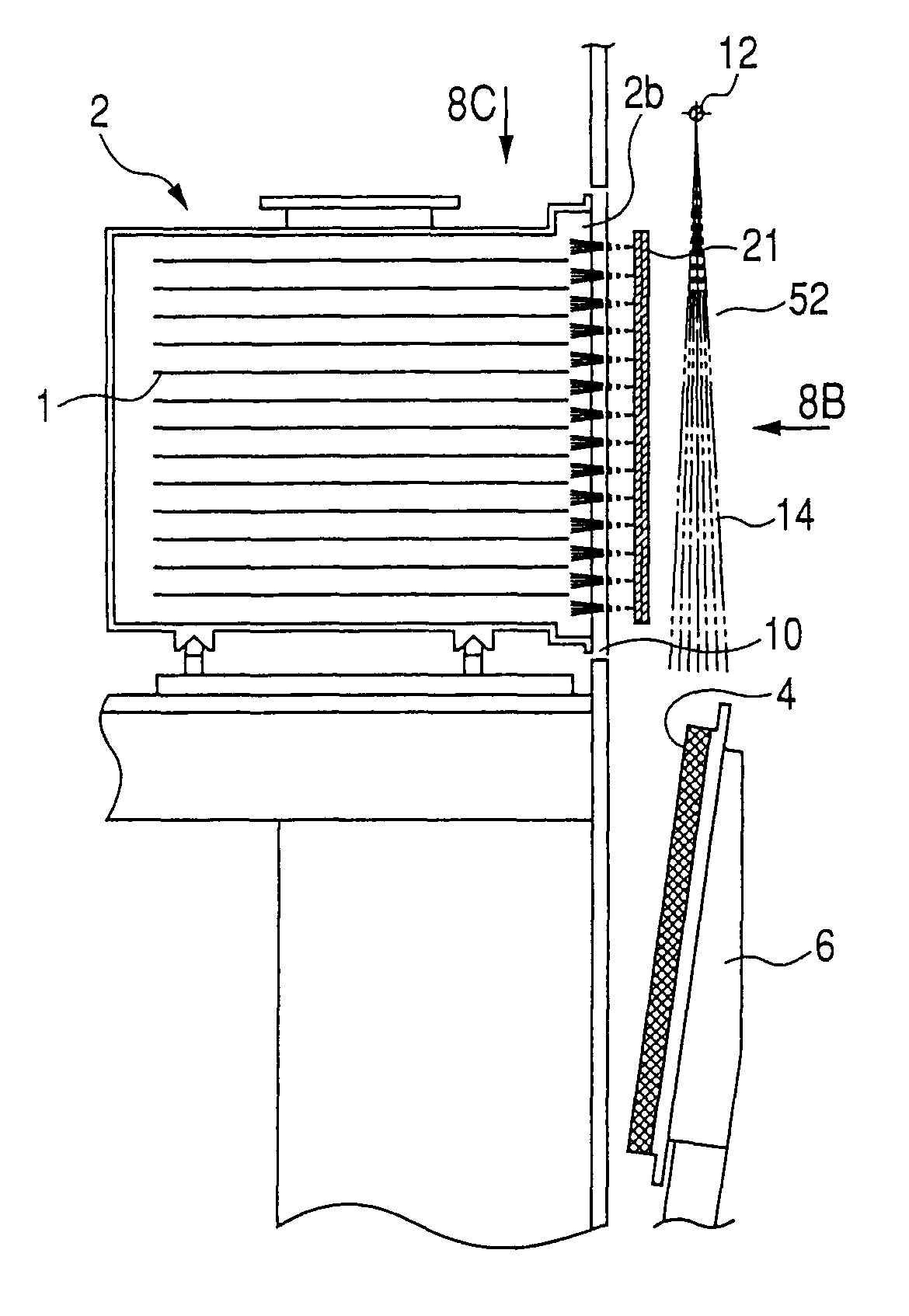
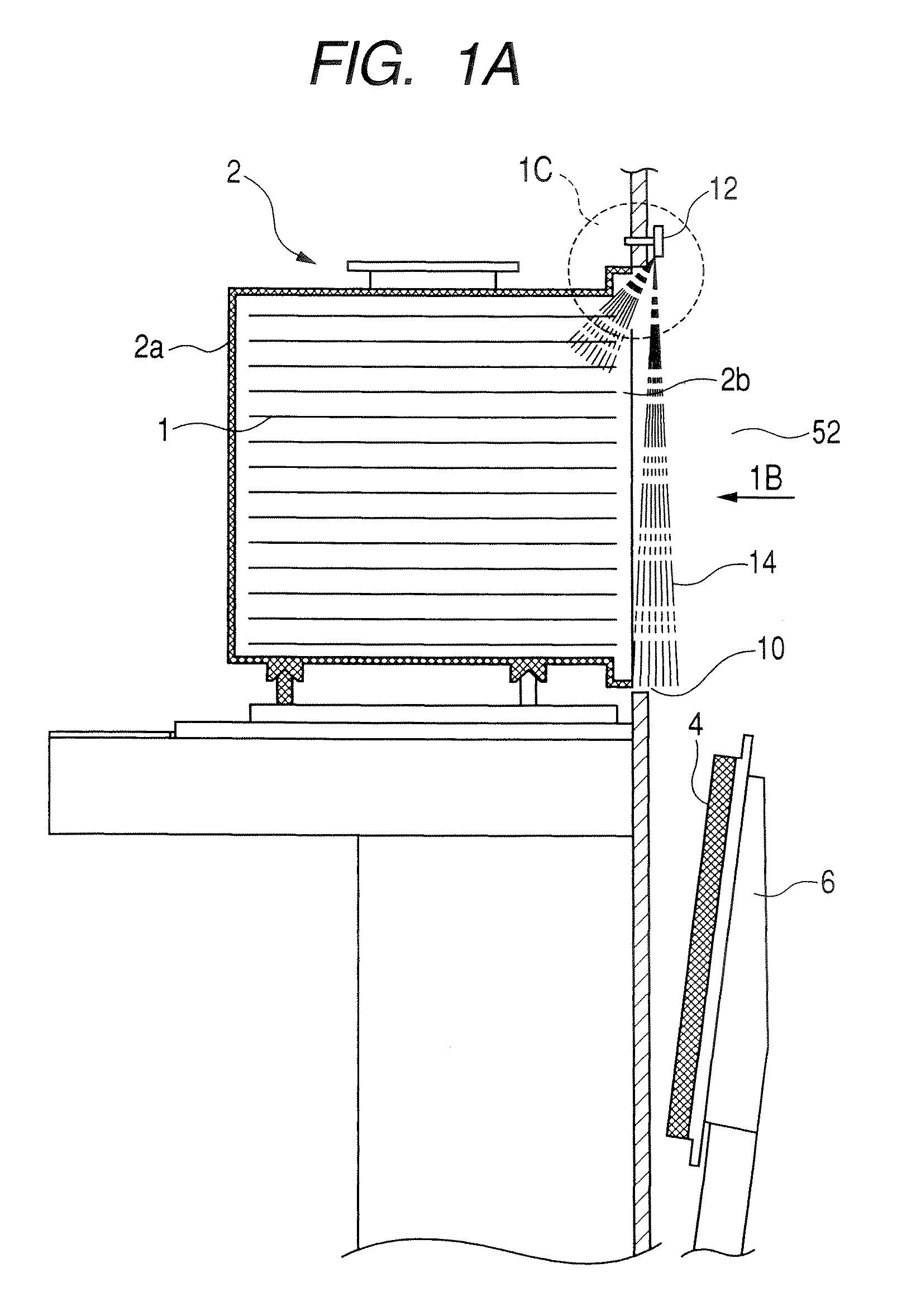
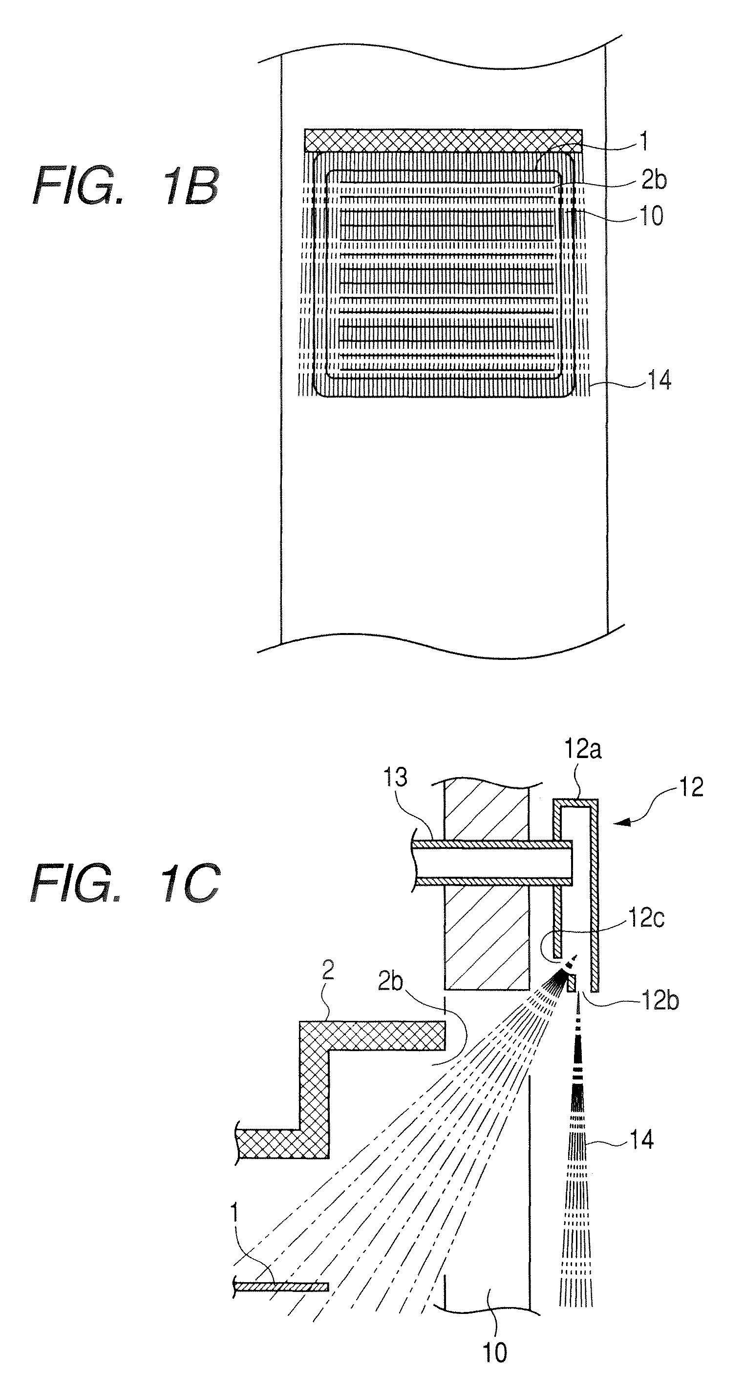
[0047]Hereinafter, embodiments of the present invention will be described with reference to the drawings. FIG. 1 is a schematic structural view of a main part of a lid opening / closing system (FIMS, hereinafter referred to as a load port) according to the present invention, that is a side-view cross section of a pod and the main part of the load port which holds the pod with a lid thereof in an open state. Note that the pod inherently includes various elements such as a rack for supporting wafers and a seal member located between the lid of the pod and the pod. Further, various elements are attached to a door and a base for supporting the pod. However, those members are not directly associated with the present invention, so the detailed illustration and description thereof will be omitted. It should be noted that in the present invention a wafer 1 described below corresponds to an object to be contained, a pod 2 corresponds to a storage container, a main body portion 2a corresponds t...

second embodiment

[0070]According to this embodiment, the plate-like member 23c along the top side decreases or prevents involvement of oxidizing gas in the gas curtain 14 supplied from the curtain nozzle 12. In other words, the main object of the plate-like member 23c along the top side is to obtain this effect, and may be in the shape of the nozzle cover of the In order to obtain the effect with regard to the gas curtain, it is sufficient that the cover is configured to define a circumferential space around the region of the nozzle opening of the curtain nozzle which ejects the inert gas to form the gas curtain flow so as to prevent any oxidizing gas from being involved in the gas curtain flow. The inert gas flow ordinarily diffuses with a larger extent as being farther from the curtain nozzle 12 where concentration of the inert gas per unit volume reduces, and as a result the curtain effect degrades. In this embodiment mode, the plate-like members 23a and 23b along the two sides prevent diffusion...


PUM

PropertyMeasurementUnit
sizeaaaaaaaaaa
structureaaaaaaaaaa
distanceaaaaaaaaaa

Abstract

A curtain nozzle is located above an opening portion (10) in a FIMS. A gas curtain formed of inert gas for closing the opening portion is formed, and at the same time, the inert gas is also supplied to an inside of a FOUP. Here, the direction of supply of the inert gas supplied to the inside of the FOUP is such that it does not have a flow component directing toward the gas flow forming the gas curtain. The above-mentioned structure prevents increase over time in a partial pressure of oxidizing gas in the FOUP fixed by a FIMS system in an open state.

Description

BACKGROUND OF THE INVENTION[0001]1. Field of the Invention[0002]The present invention relates to a so-called front-opening interface mechanical standard (FIMS) system used when wafers held in a transfer container which is called a pod are transferred among semiconductor processing apparatuses in a semiconductor manufacture process or the like. To be more specific, the present invention relates to a FIMS system which has a purging mechanism for cleaning an inside of the pod and in which the pod serving as an airtight container for containing the wafers, which is called a front-opening unified pod (FOUP), is placed and the wafers are put in and taken out from the pod for transfer of the wafer by opening / closing a lid of the pod, i.e., a lid opening / closing system.[0003]2. Related Background Art[0004]Up to now, a semiconductor manufacture process has been conducted in a so-called clean room in which semiconductor wafers are treated with high cleanliness maintained therein. However, in ...

Claims


Application Information

Patent Timeline
Patent Type & Authority Patents(United States)
IPC IPC(8): B65G1/12B65B31/04
CPCH01L21/67772H01L21/67017Y10S414/135H01L21/673H01L21/00B65G49/00
Inventor OKABE, TSUTOMU
Owner TDK CORPARATION
Why Eureka
Try Eureka