Method of processing an object in a container and lid opening/closing system used in the method

a container and container technology, applied in the field of front-opening interface mechanical standards, can solve the problems of oxidizing the surface of the wafer by oxygen or moisture, and the inability to secure the desired characteristics of the minute device,

Active Publication Date: 2009-02-05
TDK CORPARATION
View PDF10 Cites 34 Cited by
  • Summary
  • Abstract
  • Description
  • Claims
  • Application Information

AI Technical Summary

Benefits of technology

[0012]The present invention is made in view of the above-mentioned situation, and an object of the present invention is to provide a method of processing wafers, and a lid opening / closing system of a pod as an airtight container used for the method thereof, which makes it possible to control the partial pressure of oxidizing gas such as oxygen in the pod at a predetermined low level even after the pod is opened.
[0015]According to the present invention, a gas curtain is formed by a flow of inert gas in a place which is adjacent to an opening of a pod and where the opening is closed by the gas curtain, and is used as an additional path for supplying purge gas into the pod when the interior of the pod is purged. Whereas the purge operation in prior art is conducted only through a gas supply path that is originally intended for purge gas, the purge operation in the present invention can be conducted through the additional path, which speeds up the purge operation or improves the purge efficiency.
[0016]In addition, the concentration of inert gas in the inert gas flow which forms the gas curtain itself can be maintained at a high level. For example, it is known that, when gas is ejected from a nozzle, the gas involves other gas existing close to a nozzle opening and the gas mixture forms gas flow. To be more specific, because the gas forming the gas curtain involves other gas existing close to the nozzle, the concentration of inert gas forming the gas curtain decreases, and there is a fear that oxidizing gas is supplied from the gas curtain to the inside of the pod. Also, the concentration of inert gas forming the gas curtain could be lowered by surrounding gas pulled into the gas curtain. According to the present invention, a curtain cover separates the downflows constituting the surrounding gas from the curtain nozzle, or a space around the curtain nozzle, and hence a high concentration of inert gas constitutes gas in the vicinity of a nozzle opening portion as well. The curtain cover also prevents the downflows from entering an area between the wall and the lid when the flow of the gas curtain is redirected toward the interior of the pod upon contact with the lid. The present invention thus prevents the entrance or diffusion of the downflows or other gas containing oxidizing gas beyond the gas curtain which leads to this area. As a result, the infiltration of oxidizing gas into the pod can be prevented effectively.
[0017]Forming the gas curtain also reduces the diffusion of surrounding gas into the pod. The supply of inert gas to an inside of the pod is carried out in a predetermined direction so as not to affect the gas curtain. To be more specific, the gas curtain controls the entry of gas from the outside of the pod into the inside of the pod, and, at the same time, inert gas is supplied to the inside of the pod, to maintain the concentration of inert gas in the pod at a constant level. By combining those effects, even when the pod is open, the partial pressure of oxidizing gas in the pod is always maintained at a predetermined low level. Further, by combining those effects, compared with a case where the entry of oxidizing gas into the inside of a pod is prevented by simply supplying inert gas to the inside of the pod and thus a large amount of inert gas is necessary, comparable or better effect of maintaining the partial pressure of oxidizing gas at a low level can be obtained with an extremely small amount of inert gas.

Problems solved by technology

However, when such the air enters the pod, there is a fear that the surface of the wafer may be oxidized by oxygen or moisture in the air.
There is a possibility that, due to such the oxide film, desired characteristics of the minute devices can not be secured.

Method used


Image

  • Method of processing an object in a container and lid opening/closing system used in the method
  • Method of processing an object in a container and lid opening/closing system used in the method
  • Method of processing an object in a container and lid opening/closing system used in the method

Examples


embodiment

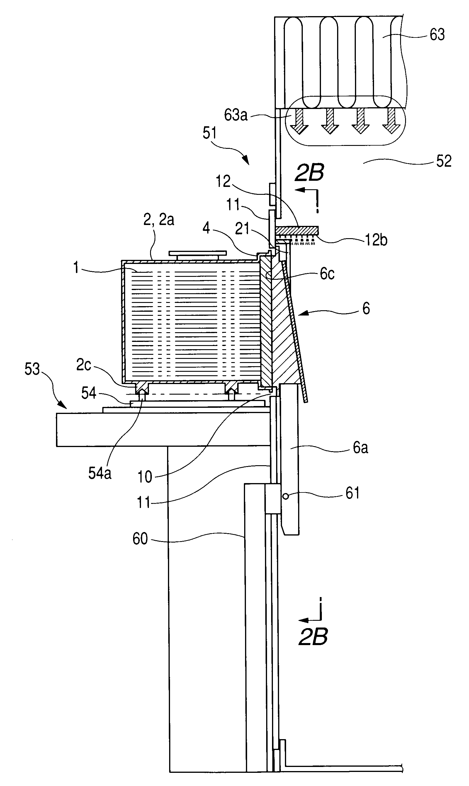
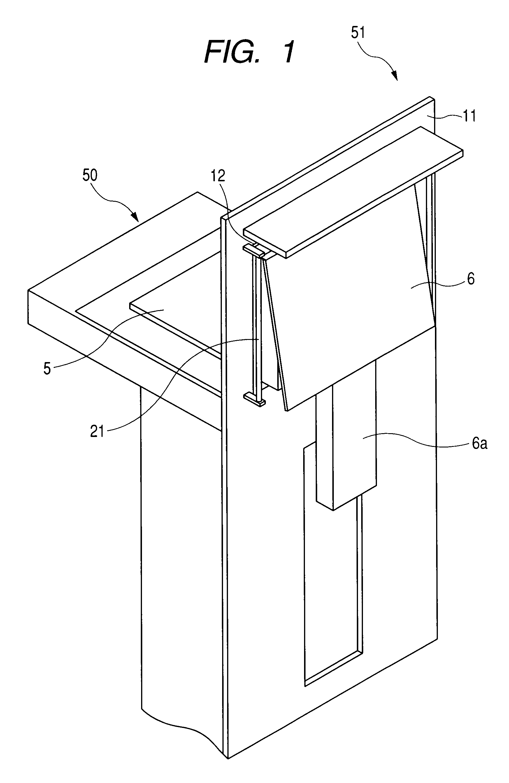
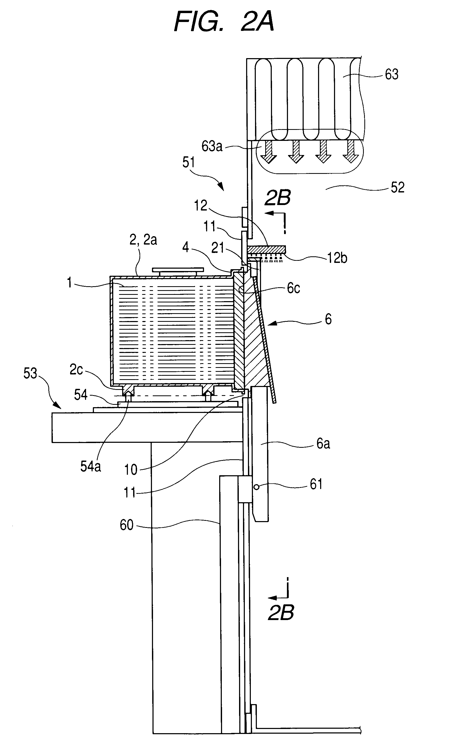
[0059]Next, a FIMS system as an actual lid opening / closing system which implements the present invention and semiconductor wafer processing apparatus using the system are described. FIG. 8 illustrates a schematic structure of a semiconductor wafer processing apparatus 50 which conforms to a so-called mini-environment system. The semiconductor wafer processing apparatus 50 is mainly formed of a load port portion (FIMS system, lid opening / closing device) 51, the transfer chamber (mini-environment) 52, and a processing chamber 59. A partition 55a and a cover 58a on the side of the load port and a partition 55b and a cover 58b on the side of the processing chamber are provided between the load port portion 51 and the transfer chamber 52 and between the transfer chamber 52 and the processing chamber 59, respectively. In order to remove contaminants and maintain high purity in the transfer chamber 52 of the semiconductor wafer processing apparatus 50, a fan filter unit 63 provided above t...


PUM

PropertyMeasurementUnit
angleaaaaaaaaaa
sizeaaaaaaaaaa
structureaaaaaaaaaa

Abstract

A partial pressure of oxidizing gas in an opened state FOUP fixed in a FIMS system is reduced when the FOUP is closed. Purge gas supply nozzles are placed outside of two vertical sides of an opening portion (10) within the FIMS. A curtain nozzle is additionally installed which can form a gas curtain from purge gas above the top side of the opening portion (10). When a pod (2) is closed with a lid (4), a door opening / closing mechanism keeps the lid (4) at a given angle with respect to the flowing direction of curtain gas for a given period of time, and hence purge gas supplied to the gas curtain is additionally put into use for the purging of the interior of the pod by the lid 4.

Description

BACKGROUND OF THE INVENTION[0001]1. Field of the Invention[0002]The present invention relates to a so-called front-opening interface mechanical standard (FIMS) system used when wafers held in a transfer container which is called a pod are transferred among semiconductor processing apparatuses in a semiconductor manufacture process or the like. To be more specific, the present invention relates to a FIMS system which has a purging mechanism for cleaning an inside of the pod and in which the pod serving as an airtight container for containing the wafers, which is called a front-opening unified pod (FOUP), is placed and the wafers are moved with respect to the pod by opening / closing a lid of the pod, i.e., a lid opening / closing system.[0003]2. Description of the Related Art[0004]Up to now, a semiconductor manufacture process has been conducted in a so-called clean room in which semiconductor wafers are treated with high cleanliness maintained therein. However, in order to cope with an ...

Claims


Application Information

Patent Timeline
Patent Type & Authority Applications(United States)
IPC IPC(8): H01L21/67
CPCH01L21/67772H01L21/67389H01L21/6773H01L21/67775Y10S414/14
Inventor OKABE, TSUTOMUEMOTO, JUNABE, TOMOSHI
Owner TDK CORPARATION
Why Eureka
Try Eureka