
Storm shutter system

a technology of storm shutters and shutters, which is applied in the direction of shutters/movable grilles, door/window protective devices, ceilings, etc., can solve the problem of not being a permanent addition to the home, and achieve the effect of convenient installation and removal

Inactive Publication Date: 2005-12-27
THE LUBRIZOL CORP
View PDF36 Cites 43 Cited by
  • Summary
  • Abstract
  • Description
  • Claims
  • Application Information

AI Technical Summary

Benefits of technology

[0015]It would be relatively easy to manufacture using existing products.
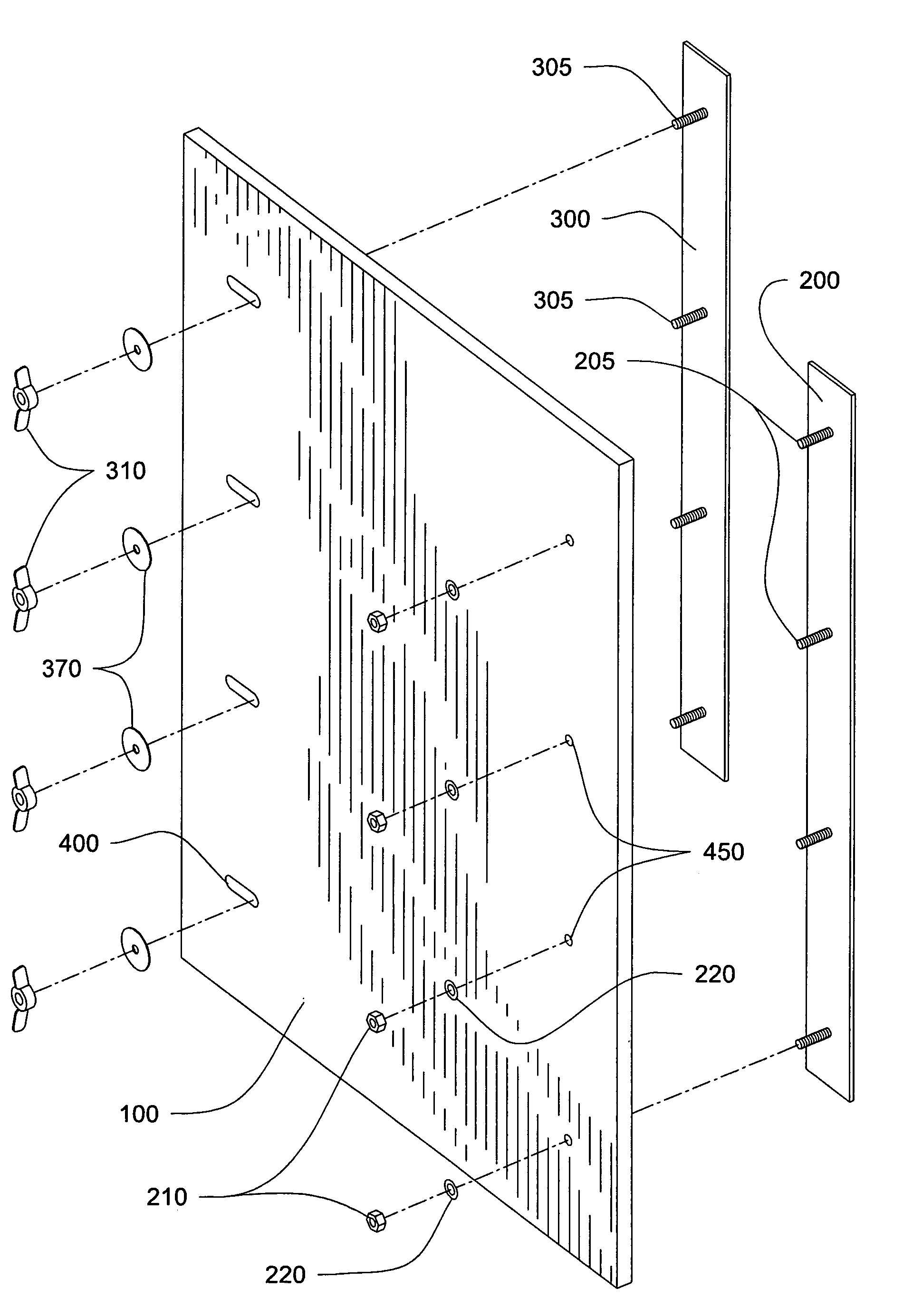
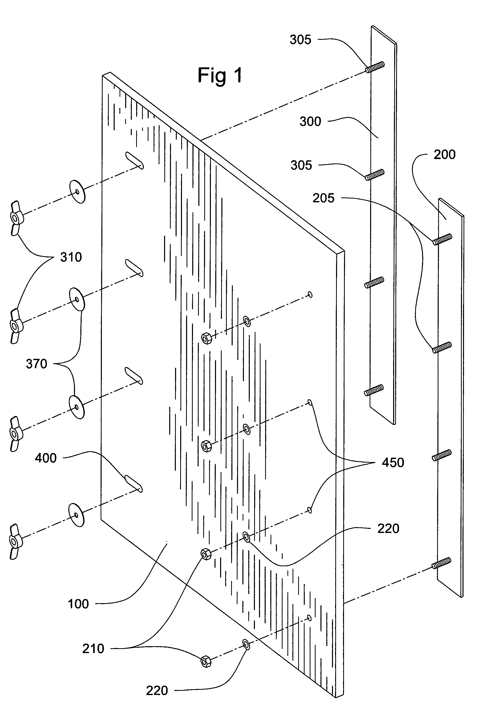
[0017]On the opposite side of the device is an identical bar. It is also attached in the same manner. However, on this side slots have been added. These slots allow the bar to move in a lateral or side-to-side fashion from one side to the other at a distance of approximately three inches. The slots will allow the user to “custom fit” the device to an existing window. The slots also insure that the fit will be a secure fit.
[0021]The device could be used on any type window and would be easy to install and remove. The choice of materials would depend on a particular manufacturer and their preference. The requirements for the choice of materials are durability and strength.

Problems solved by technology

Additionally, this is not a permanent addition to the home and the device itself can be made aesthetically pleasing for the homeowner.
Untightening the fastening devices and sliding the bar over accomplishes the removal of the device.

Method used


Image

  • Storm shutter system
  • Storm shutter system
  • Storm shutter system

Examples


Embodiment Construction

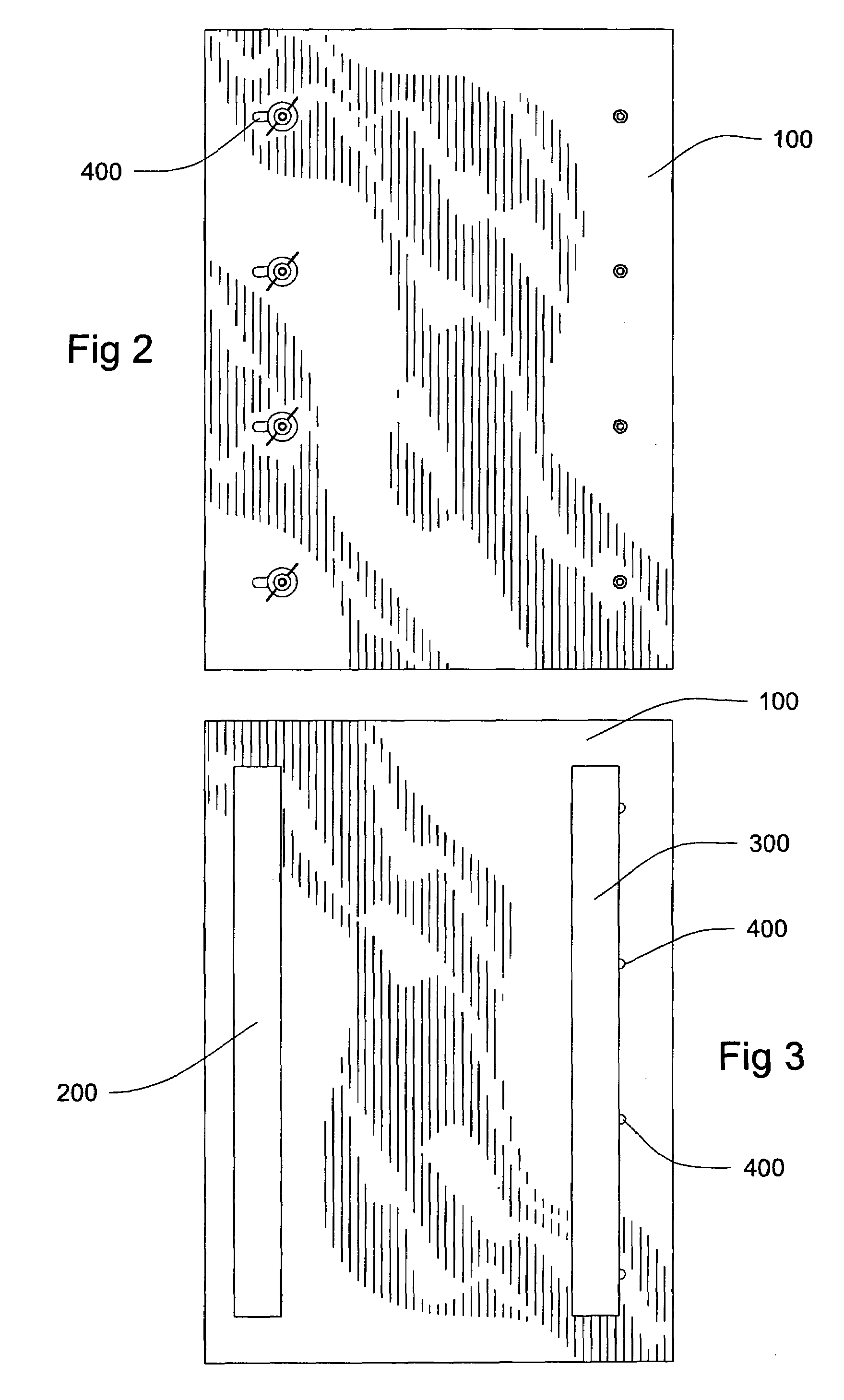
[0029]This invention is a piece of plywood, formica or other hard surface (100). As depicted in FIG. 1, the device has two bars (200, 300), which are identical but are placed on opposite sides of the device, near the outside edges of the device. One of the bars (200) is inserted through a series of holes and is attached with washers and nuts. This side of the device will remain fixed in position as the invention is used.

[0030]The other bar (300) slides from side to side by use of predrilled slots. The slots (400) have been installed so that this bar can move laterally along the surface of the device. The washers and wing nuts help attach this particular bar to the device. The wing nuts allow the bar to be moved from side to side to accommodate particular windows. As depicted in FIG. 1, the bars are of identical length and are made either of aluminum or stainless steel or other similar durable material. The choice of material in constructing the invention is not relevant, except to t...


PUM


Abstract

The embodiment of this invention is disclosed, which describes a storm shutter system, which allows easy installation and removal by the homeowner. This invention does not add anything to the window and does not require the homeowner to change the window or drill holes into the home in order to install this device. The device is installed in a temporary fashion using the existing screen track of the existing window. One side of the device used a bar, which remains, in a fixed position and the other side uses a bar with slots to allow lateral movement to insure custom fit of the device.

Description

CROSS REFERENCES TO RELATED APPLICATIONS[0001]NoneSTATEMENT REGARDING FEDERALLY SPONSORED RESEARCH[0002]No federal research money was used in the development of this invention.REFERENCE TO APPENDIX[0003]No appendix accompanies this applicationBACKGROUND OF THE INVENTION[0004]A person's largest investment during a lifetime is usually his or her home. Great care is taken to select the location of the home, the layout of the home and the parts to a home. Because of this concern the homeowner spends many hours and much money maintaining and beautifying his or her home.[0005]The present invention is used to protect windows of a home or a business during periods of inclement weather by using the screen track of the existing window in the home. In the construction of homes or businesses windows are an integral part of the construction. Most of the windows are equipped with screens. The purpose of the screen is to allow the owner to open the window and prevent the entry of foreign objects.[...

Claims


Application Information

Patent Timeline
Patent Type & Authority Patents(United States)
IPC IPC(8): E06B3/28E06B9/02
CPCE06B9/02
Inventor TRINCA, LEONARD PATRICK
Owner THE LUBRIZOL CORP
Learn More