Vibrating element liquid discharging apparatus having gas pressure sensing

Inactive Publication Date: 2005-12-27
INSTRUMENTARIUM CORP
View PDF12 Cites 94 Cited by
  • Summary
  • Abstract
  • Description
  • Claims
  • Application Information

AI Technical Summary

Benefits of technology

[0011]The present invention thus avoids the need for the separate devices heretofore used in controlling the timing of the nebulization and introduction of the nebulized liquid into the receiving flow.
[0012]Another object of the present invention is to provide an improved apparatus and method fo

Problems solved by technology

Further, due to passage of the driving gas through the nozzle, the impingement of the drug on the baffle, etc., pneumatic nebulizers tend to be noisy.
And, controlling the commencing and stopping of a drug spray is difficult and is not very accurate.
This may result in wastage of the drug.
However, ultrasonic devices require a large, bulky electrical power supply to power the crystal and may not be able to nebulizer colloidal or par

Method used


Image

  • Vibrating element liquid discharging apparatus having gas pressure sensing
  • Vibrating element liquid discharging apparatus having gas pressure sensing
  • Vibrating element liquid discharging apparatus having gas pressure sensing

Examples


Embodiment Construction

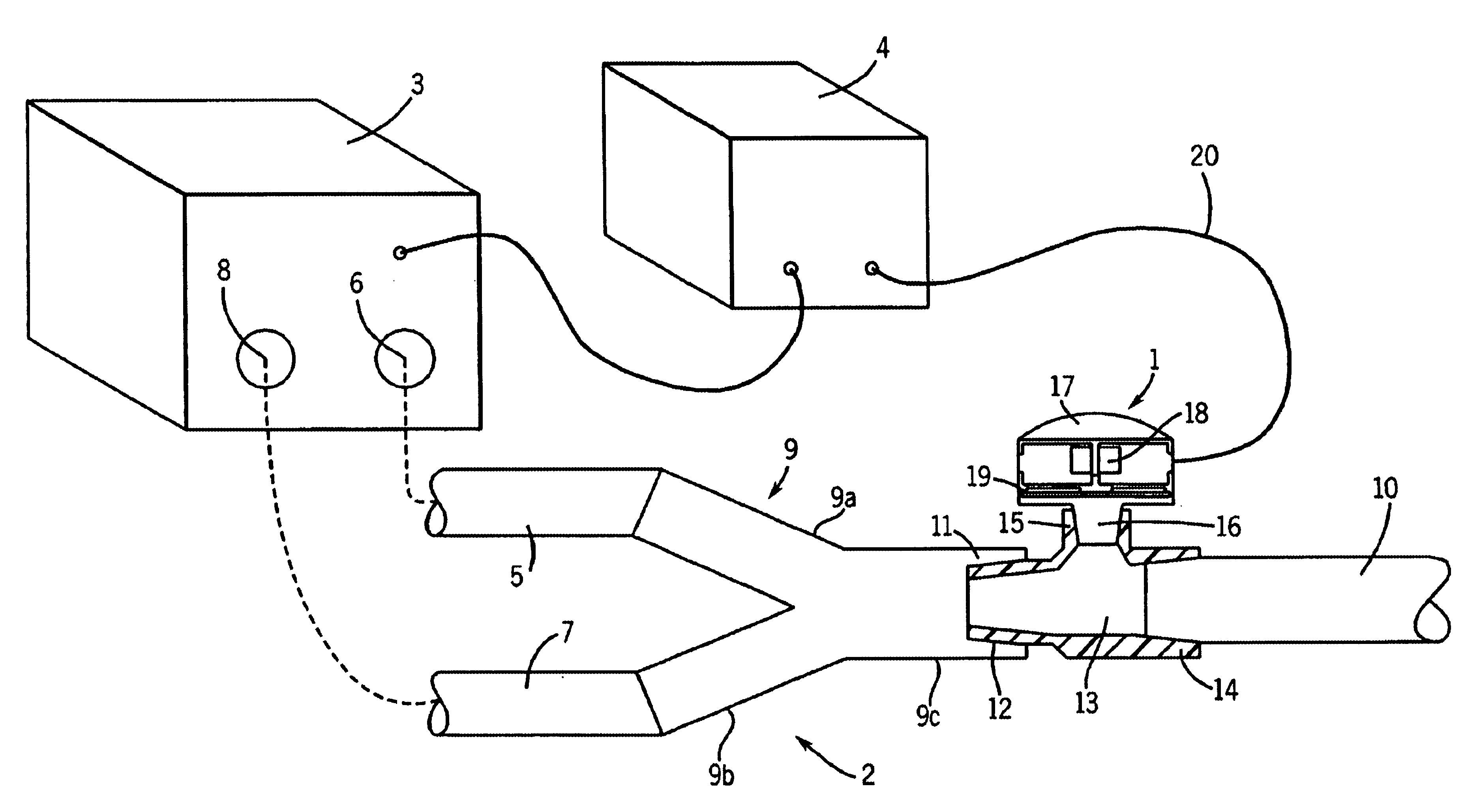
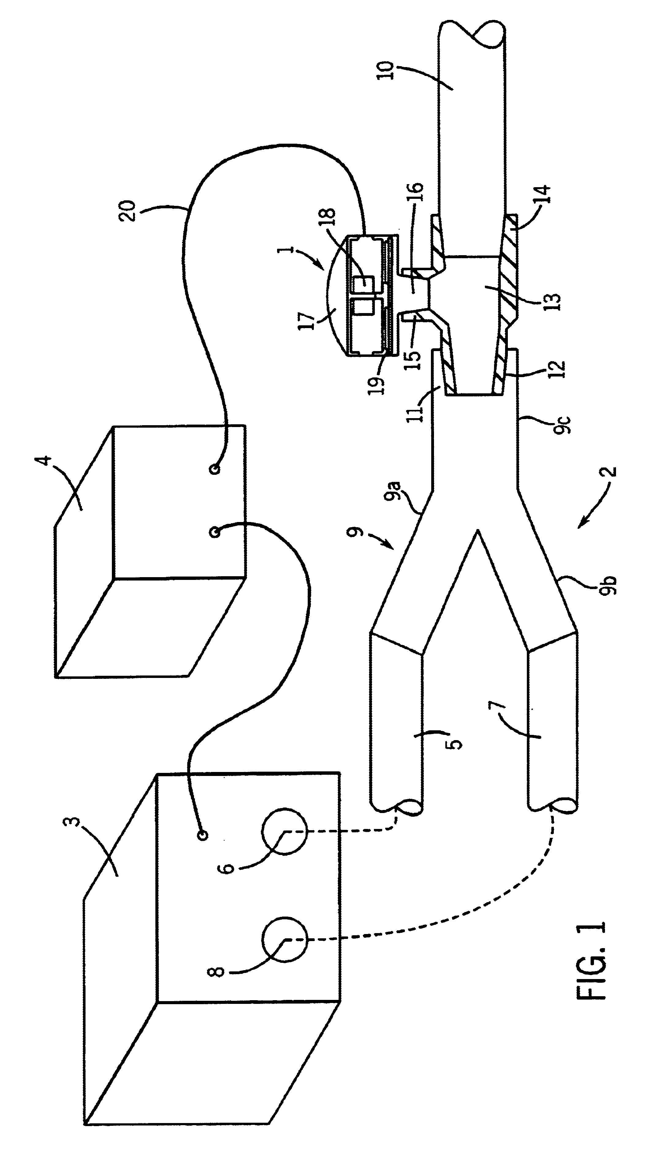
[0041]In the drawing figures, in which like reference numerals designate like parts throughout the disclosure, a fluid discharging and pressure sensing apparatus constructed according to the present invention is indicated generally by the reference numeral 1 in FIG. 1. In the application shown in FIG. 1, apparatus 1 is a nebulizer operatively connected to a breathing circuit 2 and a control unit 4. Control unit 4 is typically located separately from nebulizer 1 but may be incorporated in ventilator 3, if desired.

[0042]The substance to be nebulized typically comprises a solution, or a particulate or colloidal suspension, of a product but could comprise other substances, such as a dry fluid material. The substance may comprise water for humidification. For purposes of explanation, the fluid substance undergoing nebulization or atomization is hereinafter generally described as a liquid.

[0043]Nebulizer 1 atomizes the liquid for delivery in a breathing gas flow to a subject, for example,...


PUM


Abstract

A nebulizer determines the pressure and flow direction of the receiving gas for atomized liquid. A member of the apparatus is subjected to pressure exerted by the gas. The member is coupled to a bi-directional mechanical-electrical conversion element, such as a piezoelectric element, to form a pressure transducer. The member exerts a mechanical loading on the element responsive to the gas pressure to which it is subjected. In one embodiment, the element mechanically vibrates responsive to alternating electrical energization to discharge the liquid into the gas. The electrical admittance of the element is alterable by the mechanical loading applied to the element by the member. The difference between admittances measured in the loaded condition of the element and in an unloaded condition at the selected energization frequency is an indication of the pressure of the gas. By observing whether the magnitude of the admittance in the loaded state is greater or less than that in the unloaded state, the flow direction of the gas may also be determined. Or the flow direction may be determined by observing the changes in admittance as the frequency of the electrical energization is varied. In another embodiment, the piezoelectric element is not energized. The electrical output of the element, when subjected to a mechanical loading from the gas pressure, is used to detect gas pressures and/or as an indication of the gas pressure.

Description

BACKGROUND OF THE INVENTION[0001]The present invention relates to an improved apparatus, such as a nebulizer apparatus, for discharging fluids, and to a method of operating same. Nebulizers, or atomizers, are devices that generate a fine spray or aerosol, usually of a liquid. A particularly useful application for nebulizers is to provide a fine spray containing a dissolved or suspended particulate or colloidal pharmaceutical agent for administration to a subject by inhalation. Such inhalation treatment is highly effective for conditions affecting the subject's respiratory organs. Further, since the lungs are close to the heart and the circulatory system of the body, drug administration by inhalation provides an effective and rapid delivery system for a drug to all organs of the body. In other applications, nebulizers provide a fine spray of water for humidification.[0002]When used to dispense a pharmaceutical agent to a subject, a nebulizer in the form of an inhaler may be placed di...

Claims


Application Information

Patent Timeline
IPC IPC(8): A61M15/00A61M16/08A61M16/16
CPCA61M15/0085A61M16/08A61M16/16A61M16/147
Inventor HAVERI, HEIKKI
Owner INSTRUMENTARIUM CORP
Why Eureka
Try Eureka