Metering valve for aerosol container

Inactive Publication Date: 2005-12-27
SUMMIT PACKAGING SYST
View PDF142 Cites 57 Cited by
  • Summary
  • Abstract
  • Description
  • Claims
  • Application Information

AI Technical Summary

Benefits of technology

[0007]Another object of the present invention is to minimize the amount of separate components that must be separately assembled, during manufacture of the valve assembly, to improve the easy of assembly of the metering valve assembly.
[0008]Yet another object of the present invention is to provide a metering valve assembly which reliably, consistently and accurately dispenses a desired quantity of the product contents from t

Problems solved by technology

The installation of this additional component, during manufacture of the aerosol valve, generally increases the production costs as well as the inspection costs associated with manufacture of the aerosol valve.
Moreover, if the additional component is not properly installed or is omitted from the valve assembly for some reason, the aerosol valve will malfunction.
Another drawback associated with prior art metering valves is that such valves have a tendency to “throttle”.
That is, due to a poor or an improper valve design, it is possible for an operator to partially depress the valve stem and establish a product flow path from the interior cav

Method used


Image

  • Metering valve for aerosol container
  • Metering valve for aerosol container
  • Metering valve for aerosol container

Examples


Example

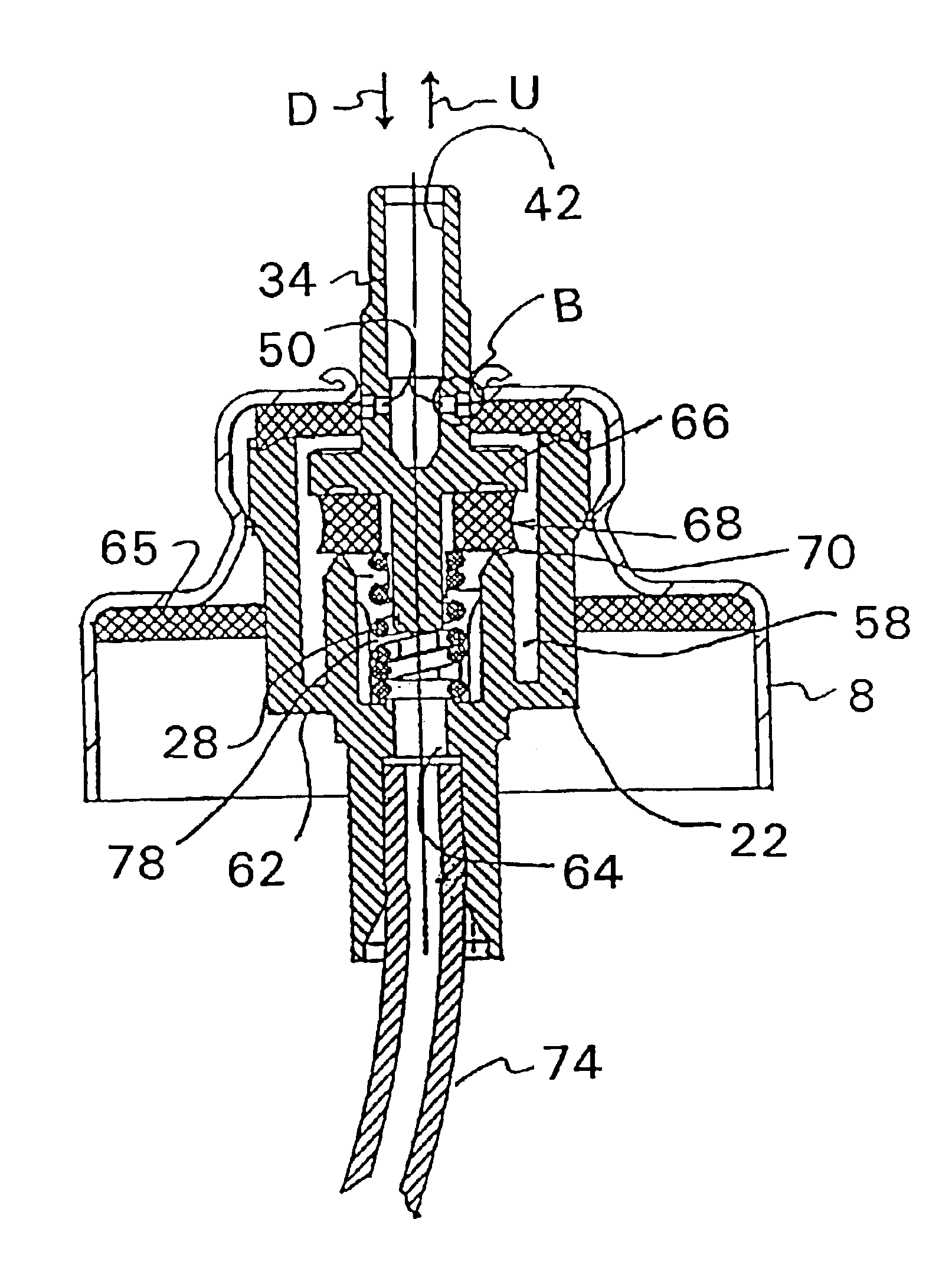
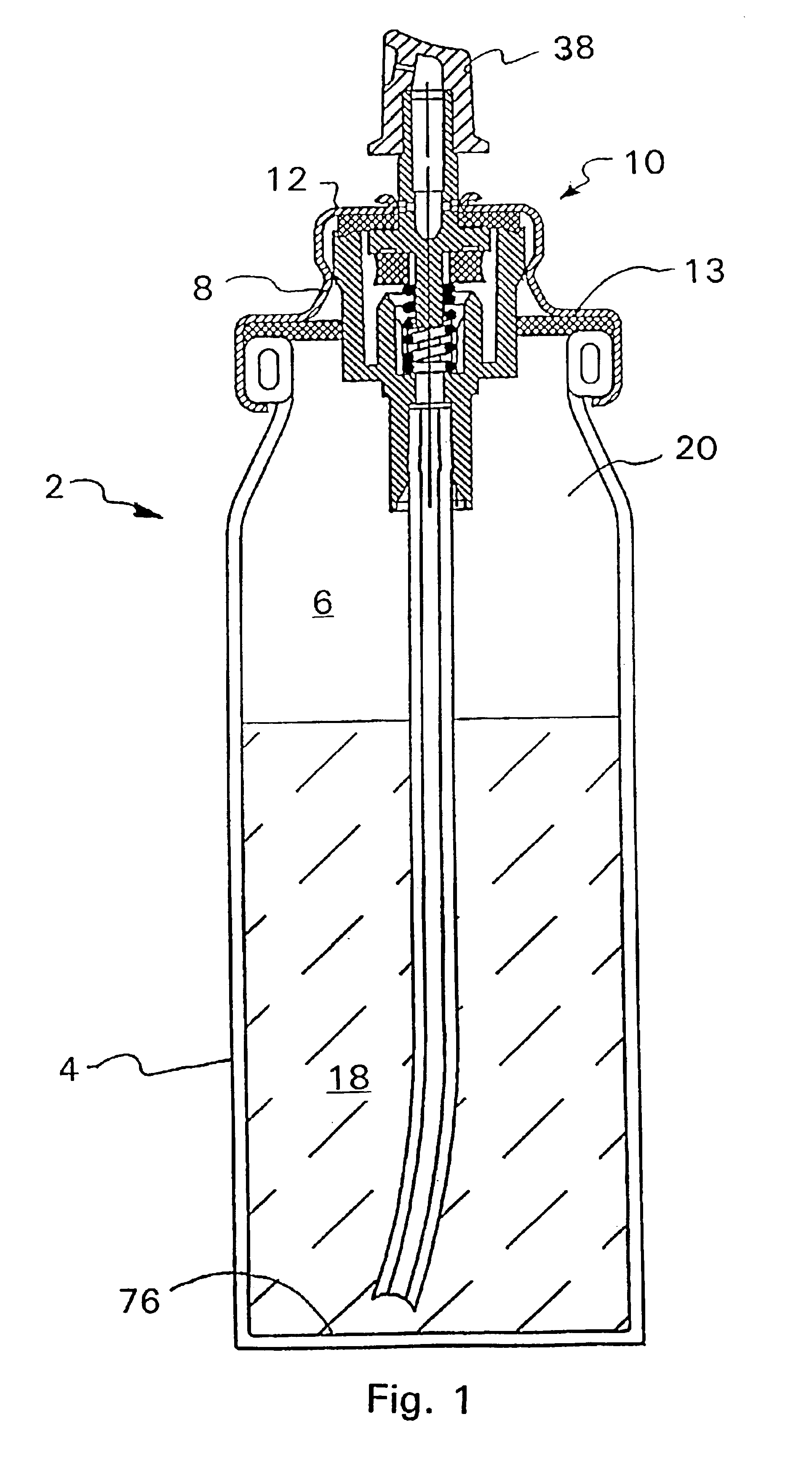
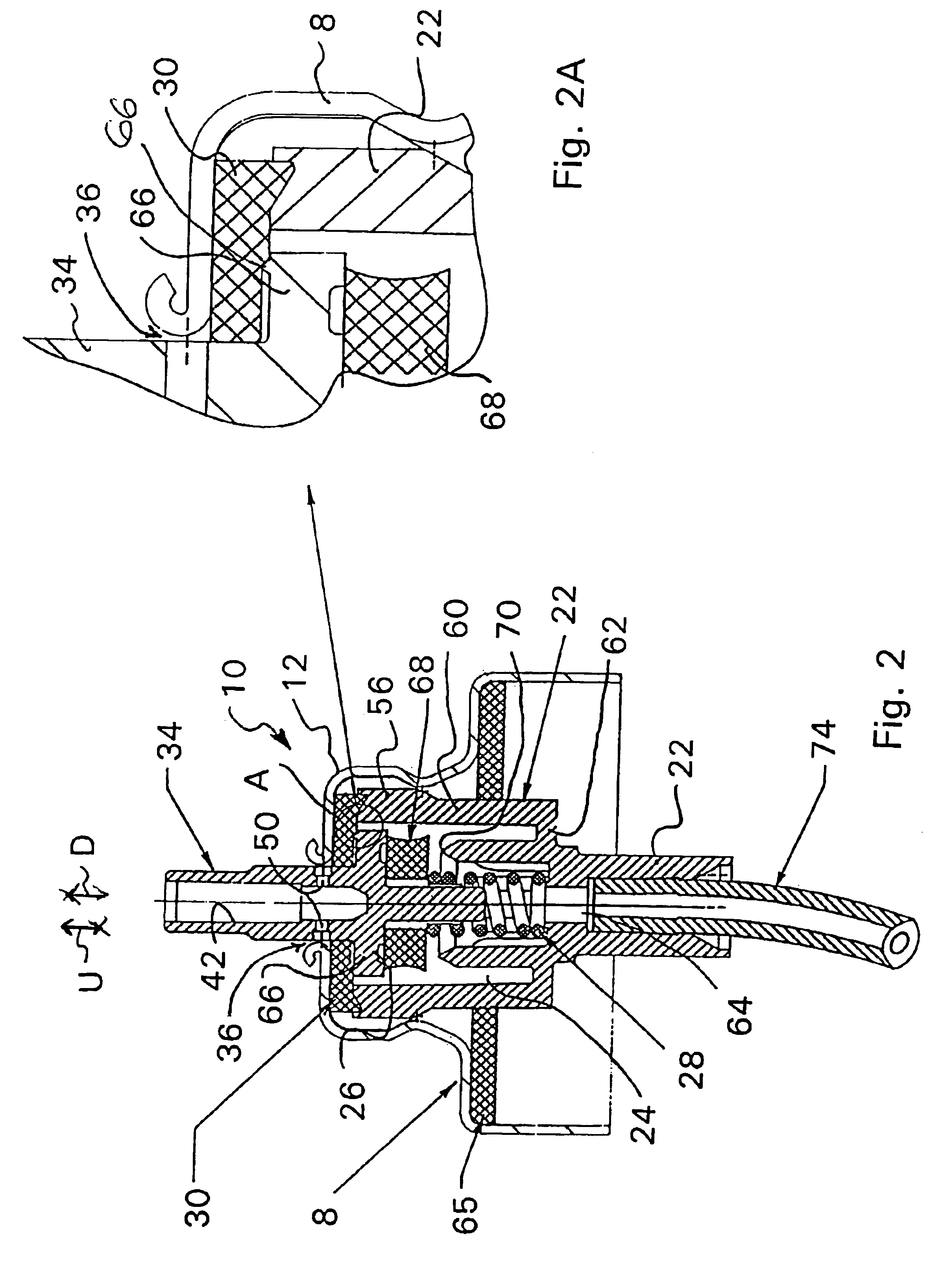
[0037]Turning now to FIGS. 2-4A, a detailed description concerning the first embodiment of the metering valve assembly, according to the present invention, will now be provided. As can be seen in these Figures, the ferrule 8 supports the metering valve assembly 10. The metering valve assembly 10 comprises a valve housing 22 having an internal cavity 24 which supports a lower portion of an upstanding valve stem 26, a compression spring 28 and a valve gasket 30. The valve stem 26 and the compression spring 28 are assembled within the internal cavity 24 of the valve housing 22 and the valve gasket 30 covers the opening of the valve housing 22 and this assembly is then clamped or crimped to the ferrule 8 via a plurality of indentations or crimps, e.g., the plurality of indentations or crimps are formed inwardly from the exterior of the sidewall of the pedestal portion 12 to permanently attach the metering valve assembly 10 to the ferrule 8. The crimping operation forces the valve housin...

Example

[0047]With reference to FIG. 4C, a second embodiment for preventing the compressible sealing member from partition or dividing the metering chamber 58 into upper and lower regions is shown and will now be described. As shown in this embodiment, a shroud, cage, sleeve, a plurality of spaced apart legs or some other component is not utilized. Rather, an inwardly facing surface, located adjacent the compressible sealing member 68, is provided with at least one pair of closely spaced ribs or some other protrusion members 71 which are located to engage with a side surface 73 of the compressible sealing member 68, during compression thereof by the valve stem 26, to prevent the compressible sealing member 68 from reconfiguring itself, expanding radially or moving radially against and completely sealing with the inwardly facing surface of the side wall 75 of the valve housing 22. The at least one pair of closely spaced ribs or some other protrusion members 71 generally abut with the side su...

Example

[0062]A fourth embodiment of the present invention will now be discussed with reference to FIG. 10. As this embodiment is very similar to the previous embodiments, a detailed description concerning only the differences between this embodiment and the prior embodiments will be provided.

[0063]As with the prior embodiments, the valve stem 26 includes an annular flange 66 which is formed integral therewith in an intermediate region of the valve stem 26. Rather than a downwardly facing surface of the annular flange 66 being provided with either a compressible sealing member 68 or sealing edge 70, the lower most end portion of the annular flange 66 has a cavity 98 or other recess which accommodates and supports a compressible sealing member 68. The compressible sealing member 68 may be adhesively secured to or otherwise permanently affixed to the cavity 98 or lower most end portion of the annular flange 66 to ensure a permanent attachment thereto or, alternatively, the compressible sealin...


PUM

PropertyMeasurementUnit
Lengthaaaaaaaaaa
Lengthaaaaaaaaaa
Volumeaaaaaaaaaa

Abstract

A metering valve assembly comprising a ferrule and a valve housing defining an internal cavity. The valve housing accommodates an annular flange and a compression spring therein with a valve gasket closing the internal cavity. The valve housing is attached to the ferrule such that a stem portion of the valve stem protrudes through apertures provided in both the valve gasket and the ferrule. A stem portion has a discharge passageway which is normally closed by the valve gasket. Either an undersurface of the annular flange or a mating surface of the valve housing is provided with a compressible sealing member while the other is provided with an annular edge. The compressible sealing member and the annular edge form a seal therebetween, when the valve stem is sufficiently depressed, to partition the interior cavity into a metering chamber and a separate filling chamber whereby product may only be dispensed solely from the metering chamber when a product flow path is established.

Description

[0001]This application is a Continuation-in-Part of Ser. No. 10 / 174,407 filed Jun. 17, 2002.FIELD OF THE INVENTION[0002]The present invention relates to a metering valve assembly for dispensing a premeasured quantity of a product from an aerosol container once the stem of the aerosol valve is sufficiently depressed.BACKGROUND OF THE INVENTION[0003]A number of metering valves are currently available in the market place. Most of these currently available metering valves utilize a ball or some other additional component which has to be separately installed in the valve housing to ensure proper metering of a desired quantity of an aerosol product from the valve assembly upon sufficient actuation or depression of the stem. The installation of this additional component, during manufacture of the aerosol valve, generally increases the production costs as well as the inspection costs associated with manufacture of the aerosol valve. Moreover, if the additional component is not properly inst...

Claims


Application Information

Patent Timeline
IPC IPC(8): B05B9/04B65D83/44B65D83/14
CPCB65D83/425B65D83/54B65D83/20
Inventor SMITH, JEREMY P.
Owner SUMMIT PACKAGING SYST
Why Eureka
Try Eureka