Surgical stapling instrument incorporating an E-beam firing mechanism

a firing mechanism and surgical stapler technology, applied in the direction of surgical staples, paper/cardboard containers, manufacturing tools, etc., can solve the problems of not being able to effectively form closed staples in severed tissue, affecting the effect of spacing

Inactive Publication Date: 2005-12-27
CILAG GMBH INT
View PDF24 Cites 3689 Cited by
  • Summary
  • Abstract
  • Description
  • Claims
  • Application Information

AI Technical Summary

Benefits of technology

[0016]The invention overcomes the above-noted and other deficiencies of the prior art by providing a firing mechanism that affirmatively vertically spaces an end effector of a surgical stap

Problems solved by technology

However, no mention is made of resisting forces that might be applied to vertically close the jaws.
However, surgeons were concerned about the pins or bumps causing tissue trauma.
Otherwise, opposing jaws may be drawn too close together, especially pinching at their distal ends, and thus not effectively forming closed staples in the severed tissue.
Moreover, a

Method used


Image

  • Surgical stapling instrument incorporating an E-beam firing mechanism
  • Surgical stapling instrument incorporating an E-beam firing mechanism
  • Surgical stapling instrument incorporating an E-beam firing mechanism

Examples


Embodiment Construction

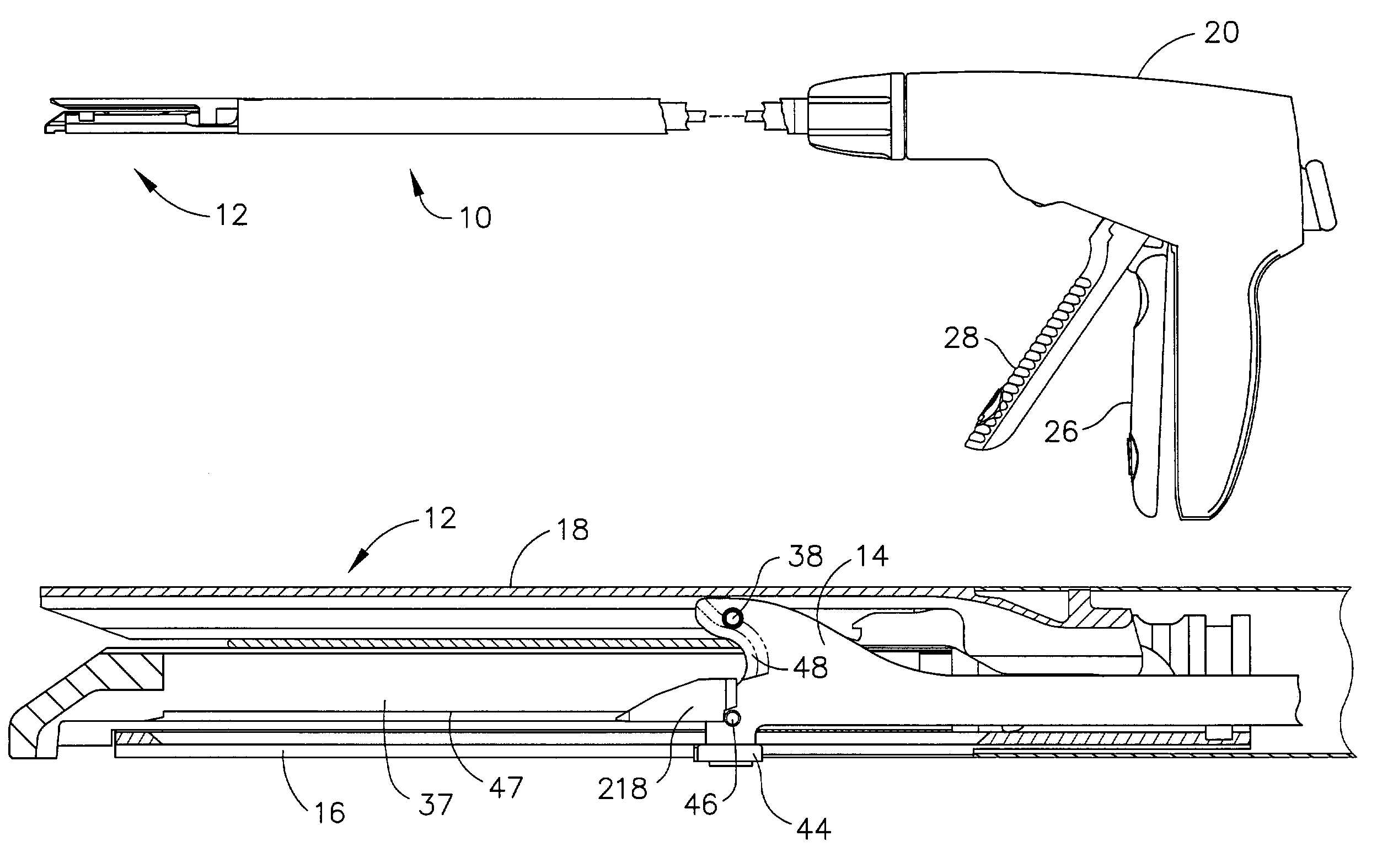
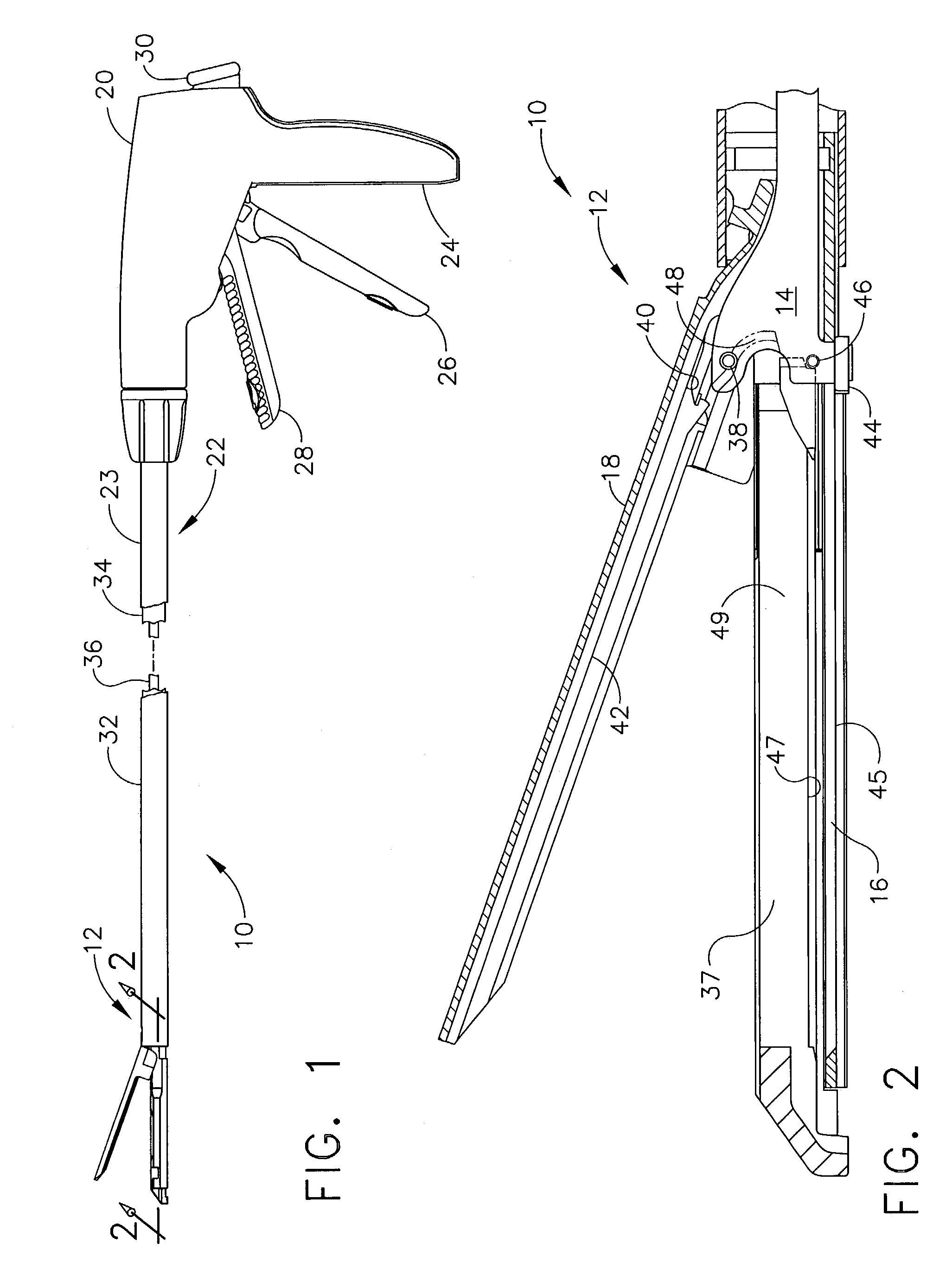
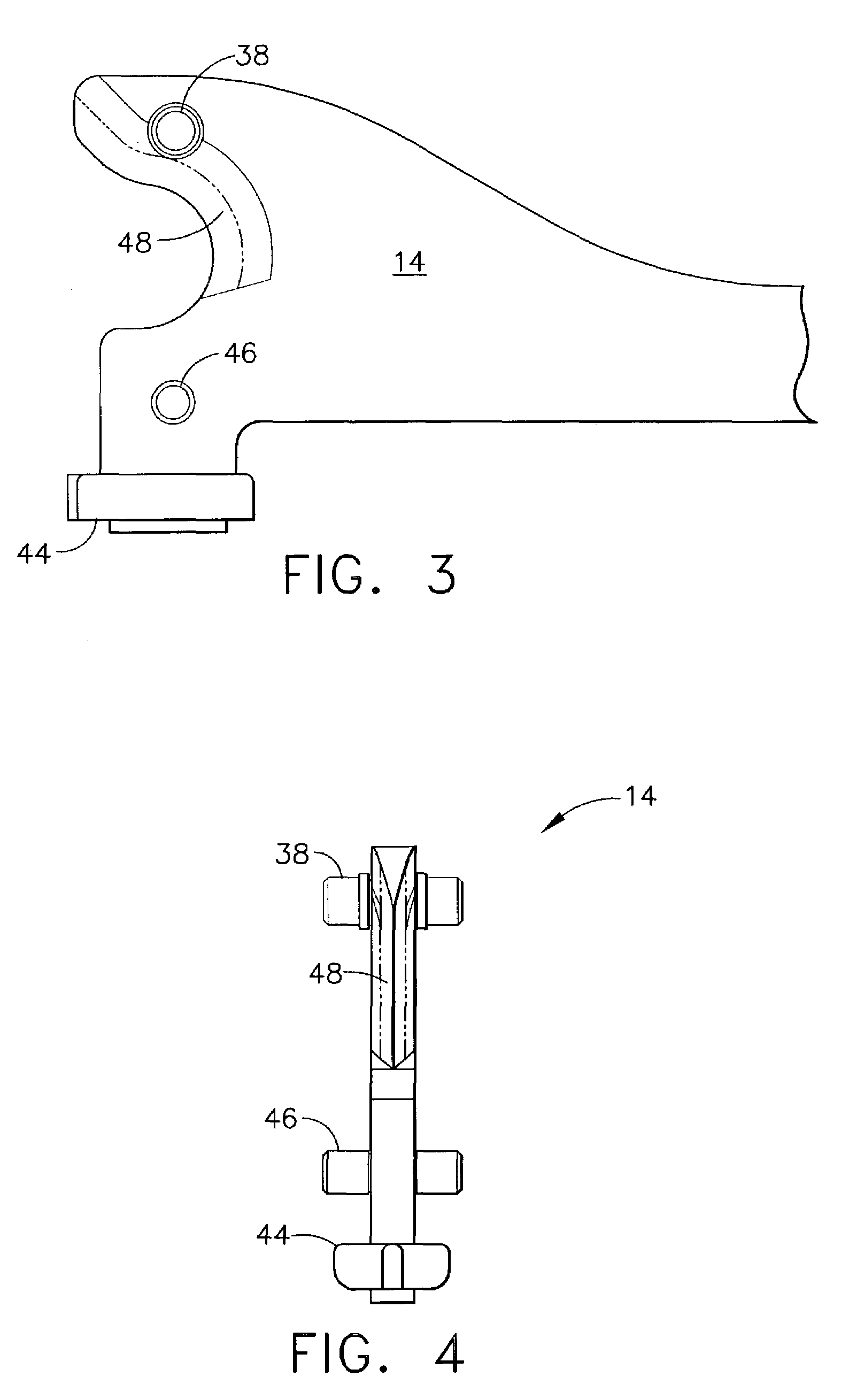
[0044]Turning to the Drawings, wherein like numerals denote like components throughout the several views, FIGS. 1 and 2 depict a surgical stapling and severing instrument 10 that is capable of practicing the unique benefits of the present invention. The surgical stapling and severing instrument 10 incorporates an end effector 12 having an E-beam firing mechanism (“firing bar”) 14 that advantageously controls the spacing of the end effector 12. In particular, an elongate channel 16 and a pivotally translatable anvil 18 are maintained at a spacing that assures effective stapling and severing. The problems are avoided associated with varying amounts of tissue being captured in the end effector 12.

[0045]The surgical and stapling and severing instrument 10 includes a handle portion 20 connected to an implement portion 22, the latter further comprising a shaft 23 distally terminating in the end effector 12. The handle portion 20 includes a pistol grip 24 toward which a closure trigger 26 ...


PUM

PropertyMeasurementUnit
Lengthaaaaaaaaaa
Thicknessaaaaaaaaaa
Heightaaaaaaaaaa

Abstract

A surgical severing and stapling instrument clamps, suitable for laparoscopic and endoscopic clinical procedures, clamps tissue within an end effector of an elongate channel pivotally opposed by an anvil. An E-beam firing bar moves distally through the clamped end effector to sever tissue and to drive staples on each side of the cut. The E-beam firing bar affirmatively spaces the spaces the anvil from the elongate channel to assure properly formed closed staples, especially when an amount of tissue is clamped that is inadequate to space the end effector. In particular, an upper pin of the firing bar longitudinally moves through an anvil slot and a channel clot is captured between a lower cap and a middle pin of the firing bar to assure a minimum spacing.

Description

CROSS REFERENCE TO RELATED APPLICATIONS[0001]The present application is related to four co-pending and commonly-owned applications filed on even date herewith, the disclosure of each is hereby incorporated by reference in their entirety, these four applications being respectively entitled:[0002](1) “SURGICAL STAPLING INSTRUMENT HAVING A SINGLE LOCKOUT MECHANISM FOR PREVENTION OF FIRING” to Frederick E. Shelton IV, Mike Setser, and Bruce Weisenburgh;[0003](2) “SURGICAL STAPLING INSTRUMENT HAVING SEPARATE DISTINCT CLOSING & FIRING SYSTEMS” to Frederick E. Shelton, Mike Setser, and Brian J. Hemmelgarn;[0004](3) “SURGICAL STAPLING INSTRUMENT HAVING A SPENT CARTRIDGE LOCKOUT” to Frederick E. Shelton IV, Mike Setser, Bruce Weisenburgh; and[0005](4) “SURGICAL STAPLING INSTRUMENT HAVING A FIRING LOCKOUT FOR AN UNCLOSED ANVIL” to Frederick E. Shelton IV, Mike Setser, and Bruce Weisenburgh.FIELD OF THE INVENTION[0006]The present invention relates in general to surgical stapler instruments tha...

Claims


Application Information

Patent Timeline
IPC IPC(8): A61B17/32A61B17/068A61B17/072
CPCA61B17/07207A61B2017/07214A61B2017/07242A61B2017/07285
Inventor SHELTON, IV, FREDERICK E.SETSER, MICHAEL EARLWEISENBURGH, II, WILLIAM BRUCE
Owner CILAG GMBH INT
Why Eureka
Try Eureka