Fat-removal massager

a massager and fat-removal technology, applied in the field of new and improved fat-removal massagers, can solve the problems of not producing squeezing and fat-removal effect upon the muscles containing much fat, and achieve the effect of rapid squeezing

Inactive Publication Date: 2005-12-27
CHEN JUNG TSUNG
View PDF5 Cites 7 Cited by
  • Summary
  • Abstract
  • Description
  • Claims
  • Application Information

AI Technical Summary

Benefits of technology

[0006]It is a primary object of the present invention to eliminate the above-mentioned drawbacks and to provide a fat-removal massager which utilizes a speed-adjustable motor in combination with two corresponding gear sets f...

Problems solved by technology

However, they can't produce squeezing and fat-...

Method used


Image

  • Fat-removal massager
  • Fat-removal massager
  • Fat-removal massager

Examples


Embodiment Construction

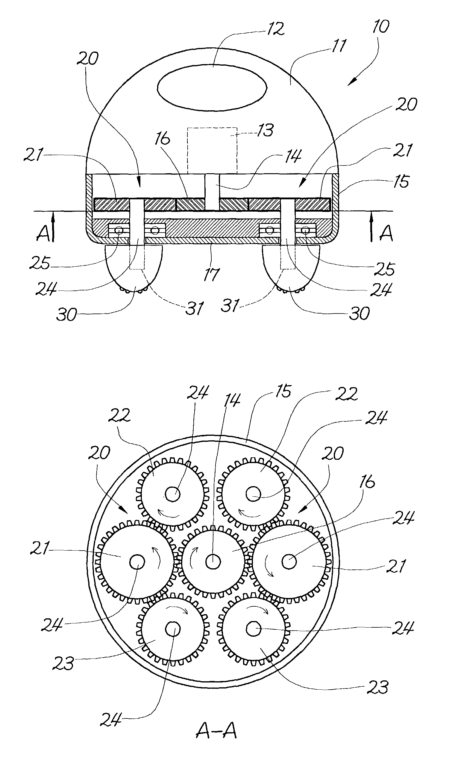
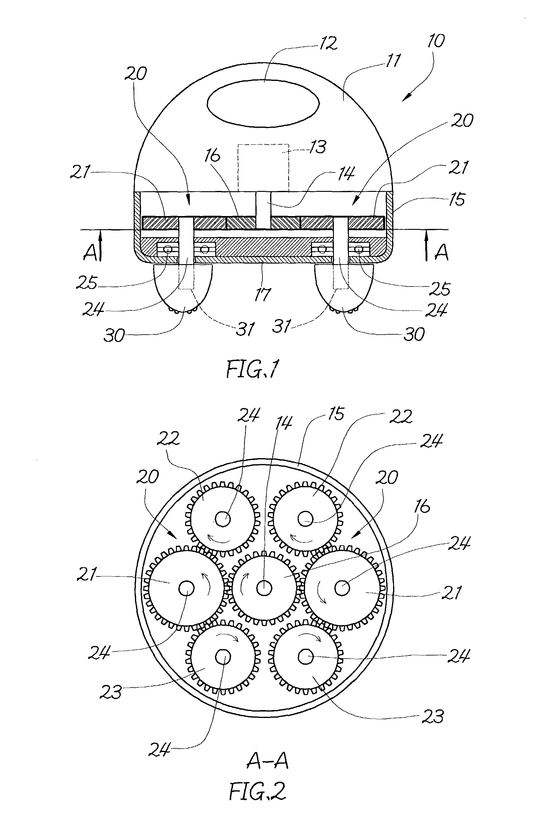
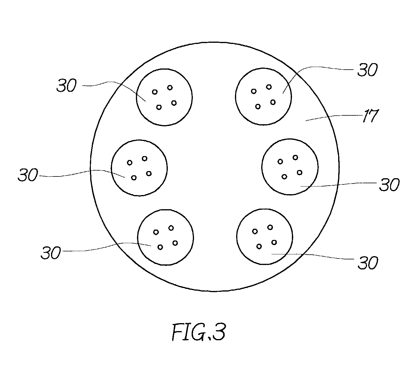
[0011]First of all, referring to FIGS. 1 and 2, a preferred embodiment of the present invention is shown. The present invention includes:[0012]a main body 10 having a handle portion 12 at the upper section 11 thereof and a speed-adjustable motor 13 within the main body, the speed-adjustable motor 13 having a shaft 14 extending downwards into the inside of the lower section 15 of the main body 10 for bringing a primary transmission gear 16 in motion;[0013]two pairs of gear sets 20 positioned within the lower section 15 of the main body 10 and arranged around the primary transmission gear 16 to form a circle, each of the gear sets 20 having a secondary transmission gear 21 and two driven gears 22, 23, each of the gears 21, 22, 23 being coupled with a massaging ball 30 by means of an axle 24 and a bearing 25, each of the massaging balls 30 being protruding outside a bottom cover 17 of the lower section 15 of the main body 10 after assembly, each of the massaging balls 30 being coupled ...


PUM


Abstract

The present invention relates to a fat-removal massager utilizing a speed-adjustable motor in combination with two corresponding gear sets for driving a plurality of eccentrically rotatable massaging balls. Moreover, every two neighboring massaging balls in rotation create a rapid squeezing effect upon muscles for achieving the expected fat-removing and massaging goal.

Description

BACKGROUND OF THE INVENTION[0001]1. Field of the Invention[0002]The present invention relates to a new and improved fat-removal massager, and more particularly, to an apparatus which can be used everywhere and held by a single hand to achieve the massaging and fat-removing effect.[0003]2. Description of the Prior Art[0004]The commercially available massagers work in the vibrating or in-place striking way. The vibrating massager makes use of the rapid vibration to achieve the relaxing and vibrating effect upon the local muscles. The in-place striking massager exerts a certain pressure on the local point (acupuncture point) of muscles to achieve the effect of relaxing muscles and nerves.[0005]The above-mentioned massagers can create relaxing effect on the local muscles. However, they can't produce squeezing and fat-removing effect upon the muscles containing much fat. Thus, it's necessary to improve them.SUMMARY OF THE INVENTION[0006]It is a primary object of the present invention to ...

Claims


Application Information

Patent Timeline
IPC IPC(8): A61H7/00A61H15/00
CPCA61H7/005A61H15/0085A61H2015/0007
Inventor CHEN, JUNG-TSUNG
Owner CHEN JUNG TSUNG
Why Eureka
Try Eureka