
Universal stent link design

a technology of stents and links, applied in the field of stent design, can solve the problems of stents preventing further interventional procedures, affecting the repair of vasculature, and affecting the repair of diseased vessels, so as to facilitate greater compression of stents, reduce the risk of complications, and maintain flexibility

Inactive Publication Date: 2005-12-27
ABBOTT CARDIOVASCULAR
View PDF2 Cites 35 Cited by
  • Summary
  • Abstract
  • Description
  • Claims
  • Application Information

AI Technical Summary

Benefits of technology

This patent describes a new design for connecting parts of a stent together called "links." These links have flexible arms that can adjust to changes occurring when delivering the stent through blood vessels. They also allow for larger amounts of expansion within the patient's body after the stent has been placed. Additionally, these links make the stent easier to compress for delivery. Overall, this design improves the flexibility of stents and makes them better suited for their intended use.

Problems solved by technology

The technical problem addressed in this patent is how to make a stent that is flexible enough to conform to the curve of a narrow artery, but also allows for effective compression to achieve a smaller delivery profile. Current stents either lack sufficient flexibility or fail to effectively compress, resulting in a bigger delivery profile than necessary.

Method used


Image

  • Universal stent link design
  • Universal stent link design
  • Universal stent link design

Examples


Embodiment Construction

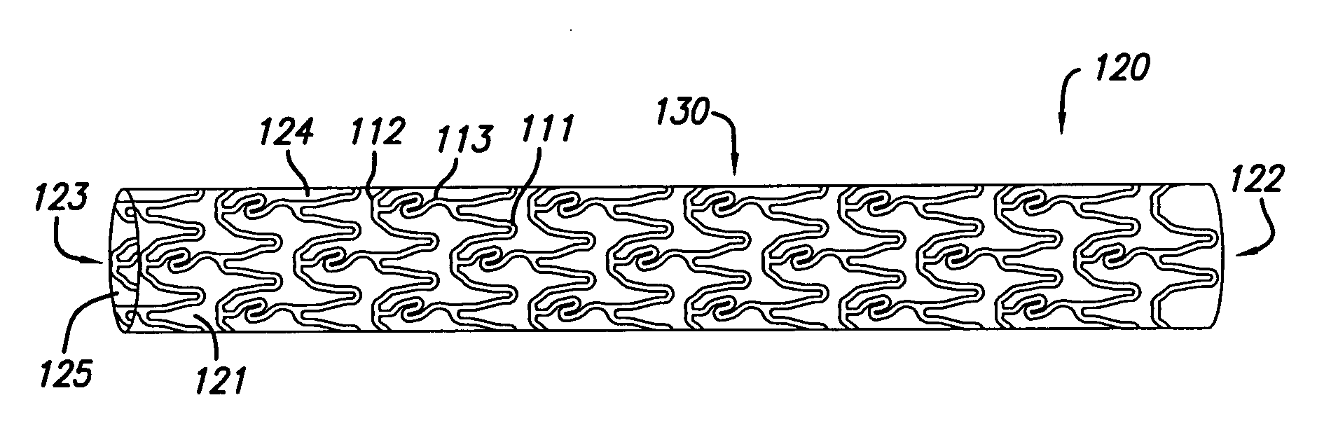
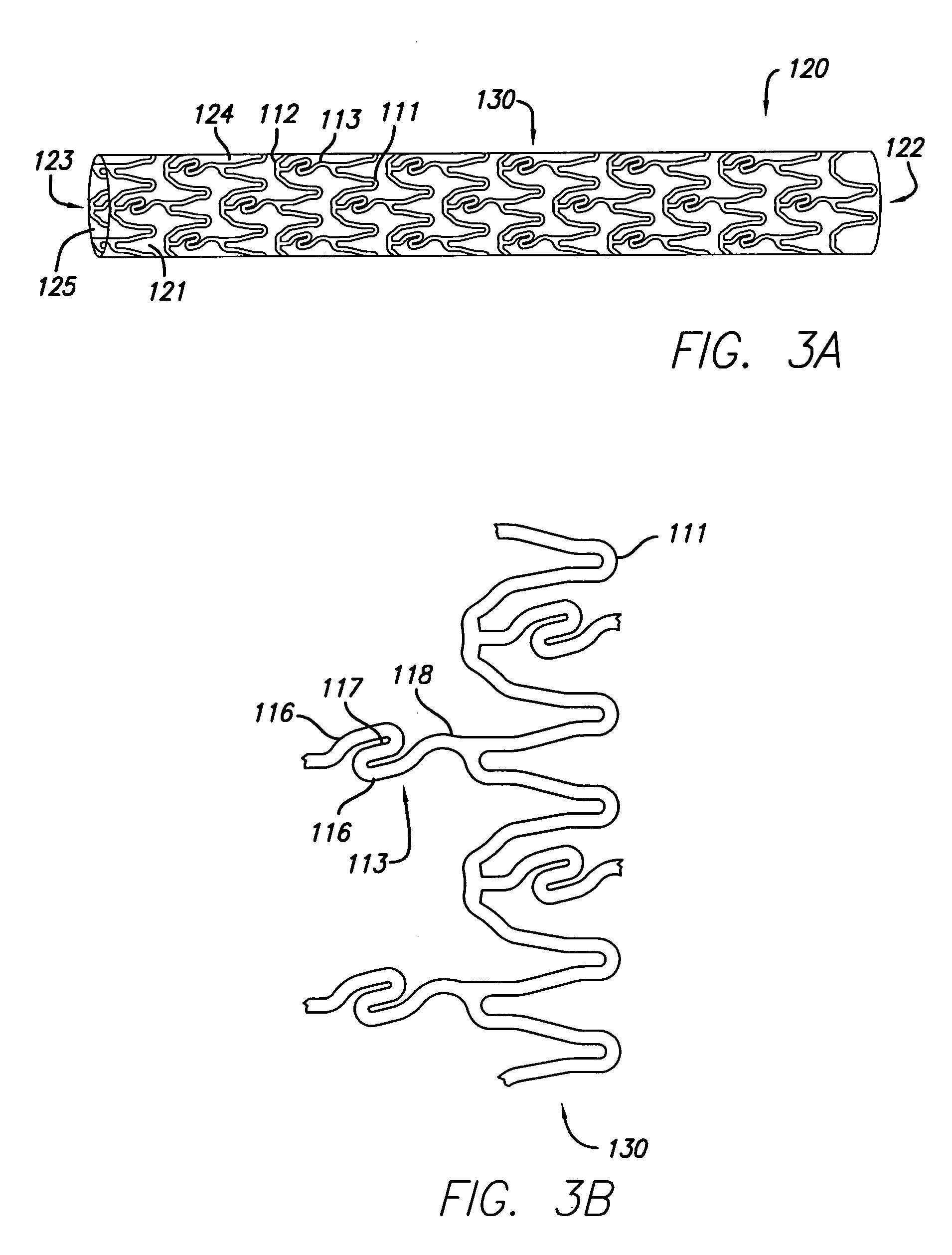
[0021]The present invention embodies a stent, and link design therefore, for repairing a vessel or whenever it is desired to increase the flexibility of a stent having rings with first peaks and second peaks, the second peaks of adjacent rings connected by links. The stent link design of the present invention incorporates short non-linear links with flexible arms, the arms having gaps between them.

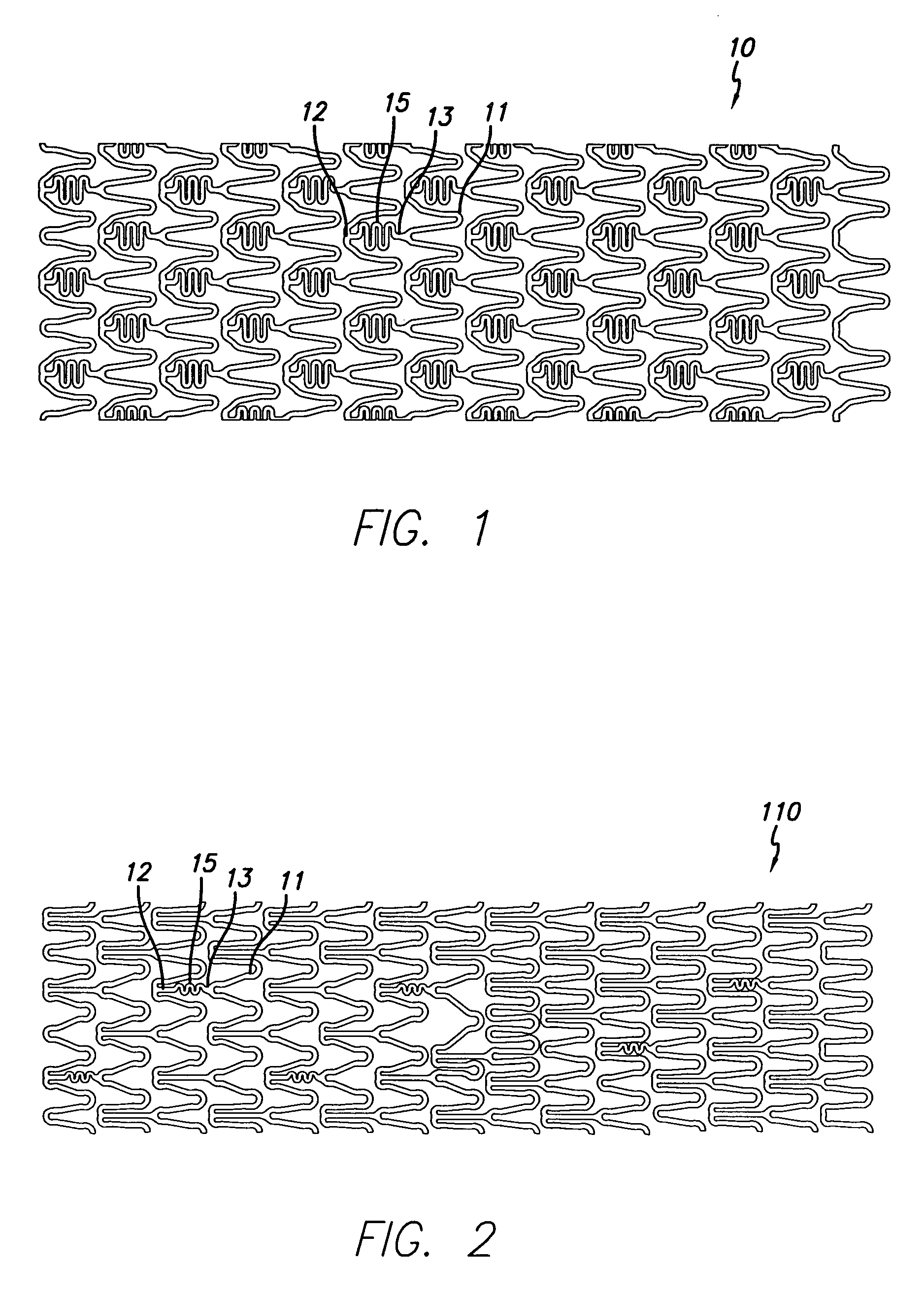
[0022]Prior art attempts at increasing the flexibility of stents by incorporating undulating portions in the links may have a detrimental effect on the compressibility of the stent and provide limited flexibility in directions other than that of a longitudinal axis of the stent, thereby accommodating only certain deformations or bending which occur during stent delivery. For example, FIGS. 1 and 2 depict prior art stents which include undulating portions in the links that connect the second peaks. FIG. 1 depicts a stent 10 having an undulating portion 15 in each link 13 between second peak...


PUM


Abstract

The present invention provides an improved stent design for repairing a vessel. The stent design incorporates crimpable, short non linear links which are flexible in three dimensions and which include flexible arms. The ability to accommodate both small deformations that occur during delivery and larger deformations that occur upon expansion within the vessel is enhanced without sacrificing stent crimp diameter. The link may incorporate a short flexible link with a perpendicular transition to provide added flexibility.

Description


Claims


Application Information

Patent Timeline
Owner ABBOTT CARDIOVASCULAR
Learn More