
Circuit for driving light source, projector, method for controlling lighting of light source, and computer readable program for executing the same

a technology for driving light sources and projectors, which is applied in the direction of electric variable regulation, process and machine control, instruments, etc., can solve the problems of insufficient heating of the electric motor of the light source, and inability to obtain the appropriate halogen cycle, so as to reduce the inside temperature of the projector, reduce the rated mode and power saving mode, and reduce the effect of reducing the inside temperatur

Active Publication Date: 2005-12-27
SEIKO EPSON CORP
View PDF15 Cites 41 Cited by
  • Summary
  • Abstract
  • Description
  • Claims
  • Application Information

AI Technical Summary

Benefits of technology

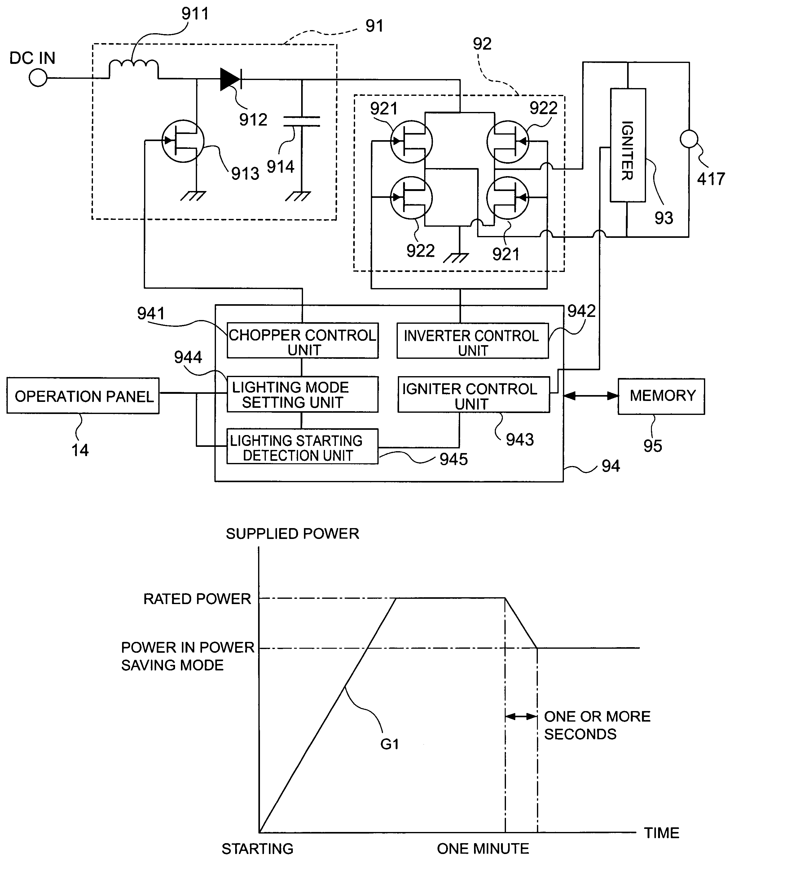
[0009]The present invention provides a circuit to drive a light source capable of coping with a rated power mode and a power saving mode and of lengthening the life span of the light source, a projector, a method of controlling the lighting of a light source, and a computer readable program for executing the same.
[0028]In addition, since the light source is lighted in the power saving mode, an increase of the inside temperature in the projector is restricted. Therefore, the number of revolutions of the cooling fan in the projector can be reduced during the operation, thereby achieving a silent or substantially silent projector.

Problems solved by technology

Thus, electrodes of the light source are insufficiently warmed, and an appropriate halogen cycle is not obtained.

Method used


Image

  • Circuit for driving light source, projector, method for controlling lighting of light source, and computer readable program for executing the same
  • Circuit for driving light source, projector, method for controlling lighting of light source, and computer readable program for executing the same
  • Circuit for driving light source, projector, method for controlling lighting of light source, and computer readable program for executing the same

Examples


Embodiment Construction

[0048]An exemplary embodiment of the present invention is explained below with reference to the accompanying drawings.

[0049](1) External Structure

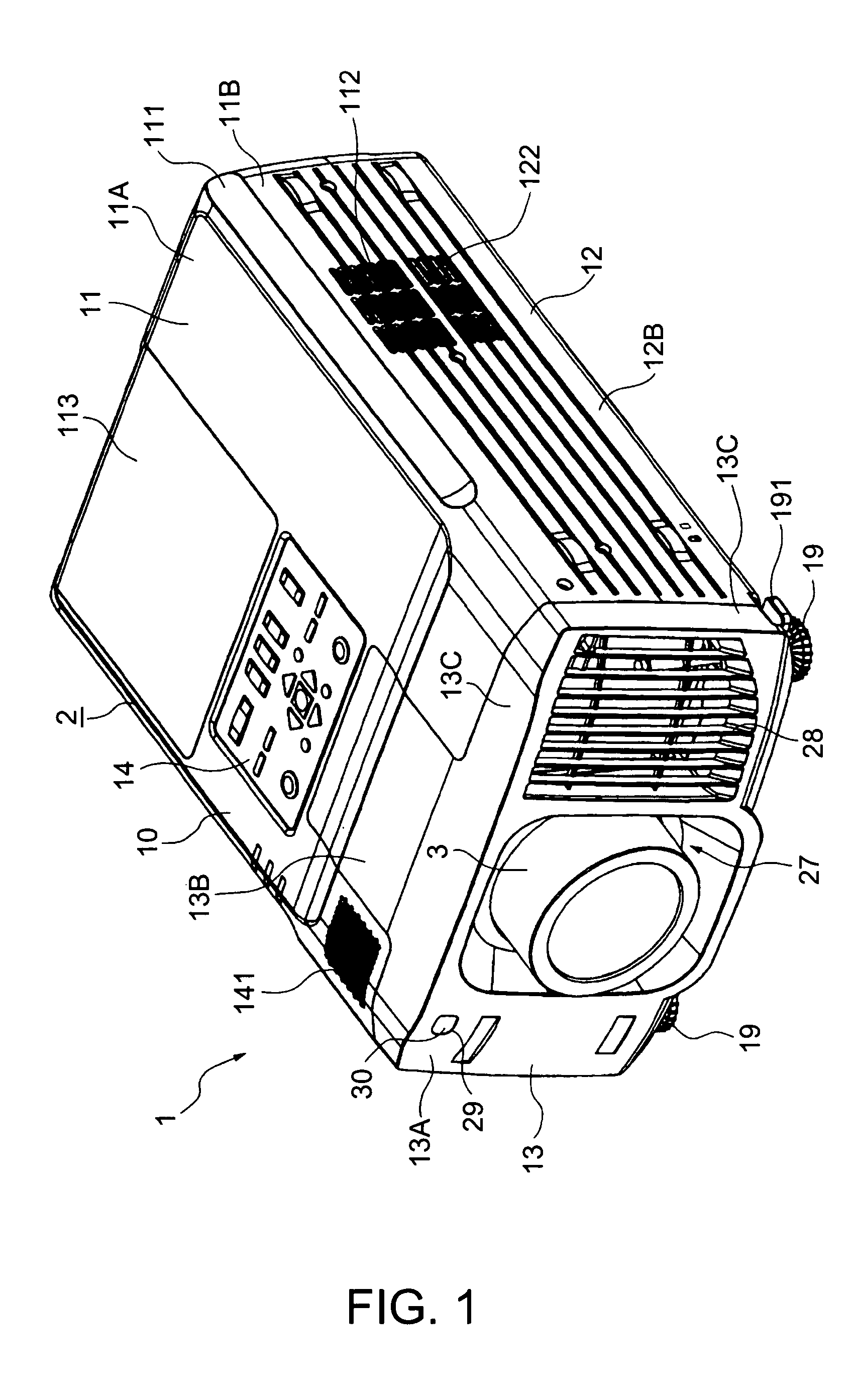
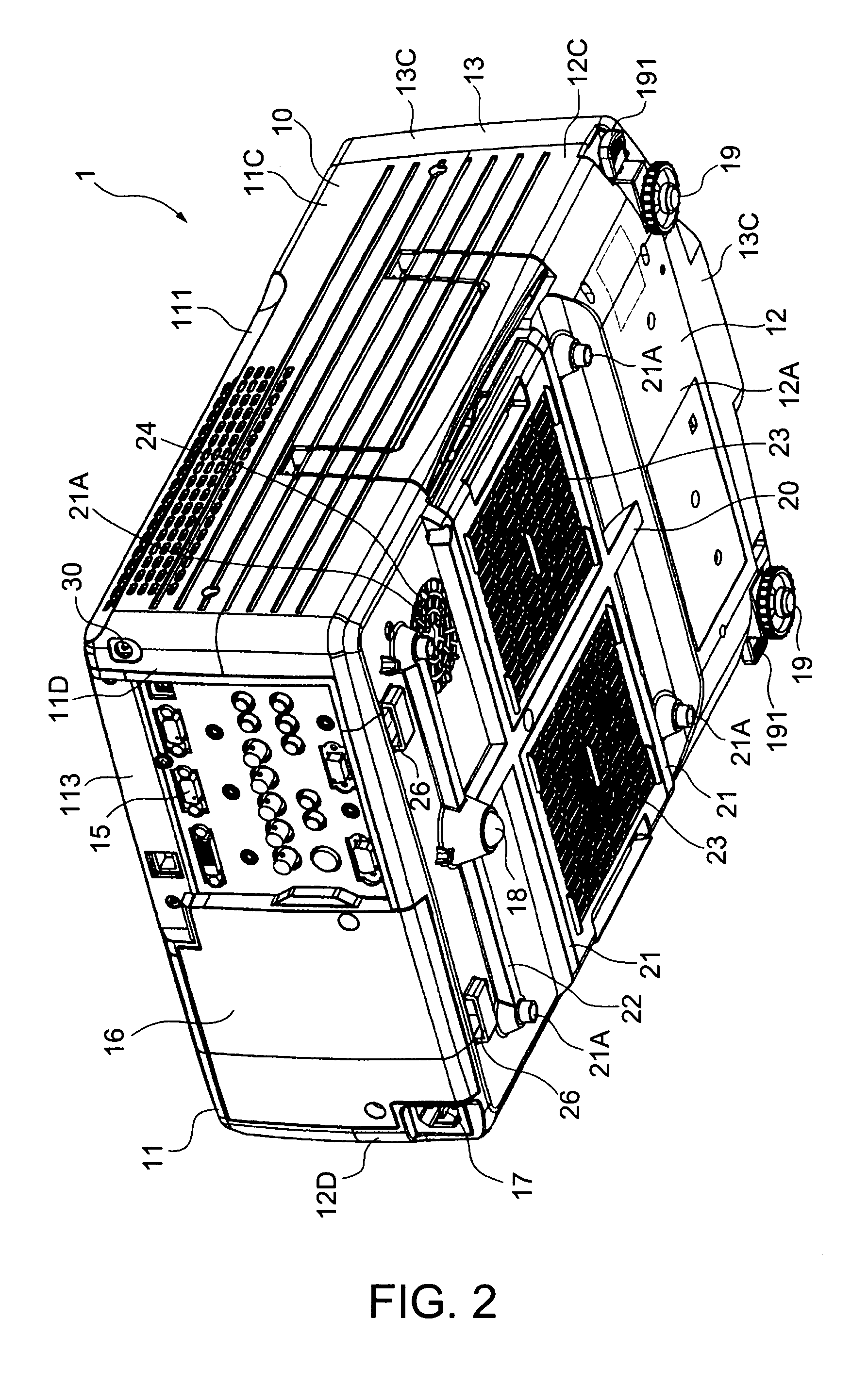
[0050]FIGS. 1 and 2 illustrate a projector 1 in accordance with one exemplary embodiment of the present invention. FIG. 1 is a perspective view as viewed from the top front side, and FIG. 2 is a perspective view as viewed from the bottom rear side.

[0051]The projector 1 is an optical apparatus to modulate beams emitted from a light source according to image information and to enlarge and protect the image on the screen. The projector 1 includes an armored case 2 to encase an apparatus main body including an optical unit (which is discussed below) and a projection lens 3 which is exposed through the armored case 2. The projector 1 is installed in a large-scaled store or public spaces to display the projected image on the screen, so that a plurality of viewers can use the image information.

[0052]The projection lens 3 performs a function of a ...


PUM

PropertyMeasurementUnit
aspect ratiosaaaaaaaaaa
voltageaaaaaaaaaa
voltageaaaaaaaaaa

Abstract

The invention provides a circuit to drive a light source capable of lengthening the life span of the light source and of coping with both a rated power mode and a power saving mode. A circuit to drive a light source includes a control device to drive the light source, which is composed of a discharge tube, and to switch the light source to a plurality of lighting modes including a rated power mode and a power saving mode. The control device includes a lighting mode setting unit to set the lighting mode to one of the plurality of lighting modes, and a rated power supplying unit to supply a rated power to the light source at the lighting starting time of the light source until a halogen cycle of the discharge tube is stabilized. The control device switches the light source to the lighting mode set by the lighting mode setting unit after the halogen cycle of the discharge tube is stabilized.

Description

BACKGROUND OF THE INVENTION[0001]1. Field of Invention[0002]The present invention relates to a circuit to drive a light source which includes a control device to drive the light source, which is composed of a discharge tube, and to switch the light source to a plurality of lighting modes including a rated power mode and a power saving mode. The invention also relates to a projector including the same; a method of controlling a light source which is executed in the circuit to drive the light source including the control device to drive the light source, which is composed of the discharge tube, and to switch the light source to the plurality of lighting modes including the rated power mode and the power saving mode; and to a program which executes the method of controlling the light source using the control device.[0003]2. Description of Related Art[0004]The related art includes projectors that can be used to modulate beams emitted from a light source according to image information, a...

Claims


Application Information

Patent Timeline
Patent Type & Authority Patents(United States)
IPC IPC(8): G02F1/13G02F1/133G02F1/13357G03B21/00G03B21/14H05B41/24H05B41/282H05B41/288H05B41/38H05B41/42
CPCH05B41/288H05B41/38H05B41/382
Inventor OKAWA, KAZUOUSHIYAMA, TOMIYOSHI
Owner SEIKO EPSON CORP
Learn More