Harbor fence

a technology of boundary fences and booms, applied in the field of surface barriers, can solve the problems of heavy security boom systems, difficult deployment and mooring, and not intended to be portabl

Inactive Publication Date: 2005-12-27
LEIDOS
View PDF12 Cites 56 Cited by
  • Summary
  • Abstract
  • Description
  • Claims
  • Application Information

AI Technical Summary

Benefits of technology

[0006]A harbor fence system may be deployed in water around ships or other waterfront assets to serve as a line-of-demarcation (visible day or night or in fog) to warn boats to stay out of the enclosed “security zone” or exclusion zone” and to provide warnings and the location of any attempted intrusion across the harbor fence system. The harbor fence system may be lightweight and portable, capable of being transported on different sizes of ships (such as a navy ship), and deployed in different harbors where a ship may dock throughout the world in order to establish a security perimeter. The harbor fence may also be used to protect commercial ships, e.g. tankers and cruise lines) or other waterfront assets (e.g. buildings and bridges) abutting harbors, lakes, or rivers.
[0007]In one embodiment of the invention, a harbor fence system comprises a series of spars that protrude above the water surface, that are spaced approximately uniformly, and that are connected to an electrical computer with a telemetry subsystem. Each spar contains electronic sensors, e.g. water immersion sensors and accelerometers, and circuitry to detect intrusions and to communicate the location of the intrusion to a computer control station on shore or on the watch deck of the associated ship. The embodiment also facilitates deploying and retrieving the harbor fence system.

Problems solved by technology

Potential threats to the waterfront asset may originate at the surface of the water or below the surface of the water that abuts the asset.
Security boom systems are typically heavy, usually difficult to deploy and moor, and are not intended to be portable.
Moreover, security booms usually cannot be seen at night or in fog or rain, and do not provide any indications of intrusion.

Method used


Image

  • Harbor fence
  • Harbor fence
  • Harbor fence

Examples


Embodiment Construction

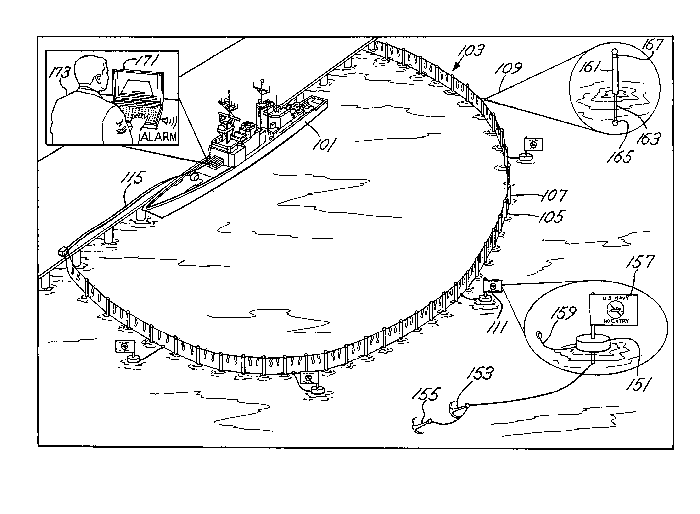
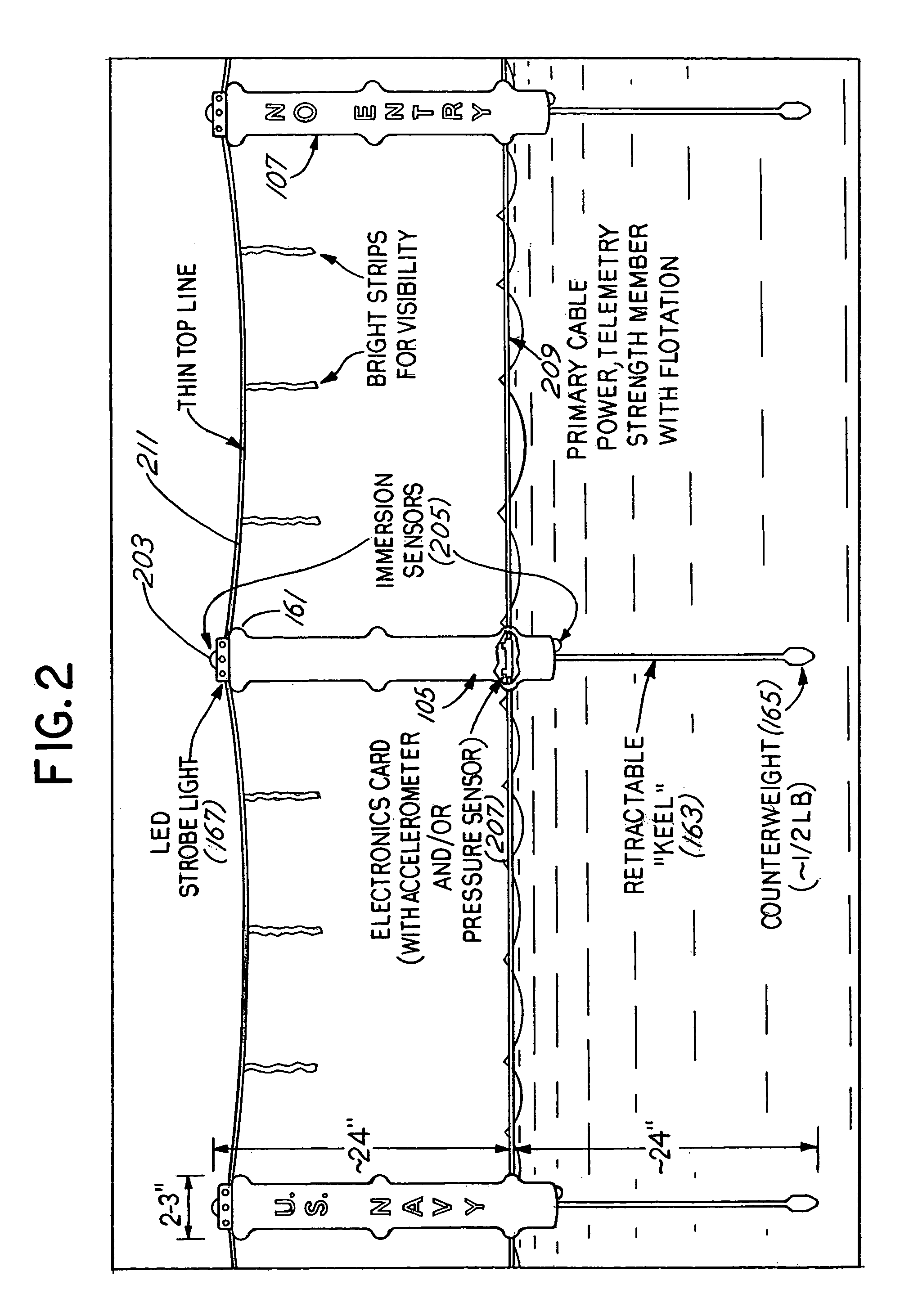
[0038]FIG. 1 illustrates a ship 101 that is protected by a harbor fence system 103 according to an embodiment of the invention. Ship 101 is moored along a pier that abuts a harbor. Variations of the embodiment may protect other types of waterfront assets (e.g. commercial ships, bridges, and buildings) that abut other types of bodies of water (e.g. rivers or lakes). Harbor fence 103 comprises a plurality of spars (“fenceposts”), e.g. spars 105, 107, and 109. The plurality of spars is connected together by a cable at the waterline containing multiple wires and by a thinner top line containing at least one wire (as shown in FIG. 2). A shape of harbor fence 103 is maintained by moors, e.g. moor 111. Moor 111 comprises a floating platform 151 that is anchored by anchors 153 and 155, that provides a base for flag 157, and that is connected to harbor fence 103 through connector 159. Spar 109 comprises an upper section 161, a LED strobe light 167, a retractable keel 163, and a counterweight...


PUM


Abstract

Methods and apparatus determine if an intruder passes into a security zone that is associated with a waterfront asset. An embodiment of the invention provides a harbor fence system that is designed to be deployed in water around ships or other waterfront assets to serve as a line-of-demarcation in order to provide protection. The harbor fence system comprises a series of spars that protrude above the water surface and that communicate with a computer with a telemetry subsystem. Each spar contains electronic sensors, e.g. water immersion sensors and accelerometers, and circuitry to detect an intrusion and to communicate the location of the intrusion to a computer control station. Spars may communicate wirelessly and may also be solar powered. Additionally, the embodiment may also determine whether an underwater intruder is passing under a protective boundary, in which the harbor fence system interfaces to an underwater sonar sensor subsystem.

Description

[0001]This application is a continuation-in-part of common-owned, U.S. application Ser. No. 10 / 365,357 filed on Feb. 12, 2003 now U.S. Pat. No. 6,778,469 naming Larry R. McDonald as inventor, the entire disclosure of which is hereby incorporated by reference.[0002]The U.S. Government has a paid-up license in this invention and the right in limited circumstances to require the patent owner to license others on reasonable terms as provided for by the terms of N41756-02-C-4682 awarded by the U.S. Navy.FIELD OF THE INVENTION[0003]The present invention relates to a surface barrier to protect an asset such as a ship that abuts a body of water.BACKGROUND OF THE INVENTION[0004]There are numerous situations in which a waterfront asset, such as military and civilian ships, that are situated in a harbor environment must be protected. Potential threats to the waterfront asset may originate at the surface of the water or below the surface of the water that abuts the asset. Typically, protective ...

Claims


Application Information

Patent Timeline
Patent Type & Authority Patents(United States)
IPC IPC(8): B63G9/00B63G9/04B63J99/00G01S7/00G01S15/87
CPCB63G9/04G01S7/529G01S7/539G01S7/54G01S15/04G01S15/66G01S15/87B63G2009/005G01S7/003G01S15/876
Inventor MCDONALD, LARRY R.
Owner LEIDOS
Why Eureka
Try Eureka