Router apparatus using ATM switch

a technology of atm switch and router, which is applied in the direction of data switching network, multiplex communication, digital transmission, etc., can solve the problem of restricted network use practicability, and achieve the effect of enhancing the multiplicity of communications

Inactive Publication Date: 2005-12-27
HITACHI LTD
View PDF35 Cites 11 Cited by
  • Summary
  • Abstract
  • Description
  • Claims
  • Application Information

AI Technical Summary

Benefits of technology

[0012]Therefore, the present invention has an object to provide a router apparatus which enhances the multiplicity of communications performed through an ATM switch.
[0013]Further, the present invention has another object to provide a router apparatus which reduces the delay variation between communications of different multiplexing transmission paths.
[0016]According to the router apparatus as described above, the processing of the packet switching type layer 3 and the cellularizing processing are performed in each interface, and the cell multiplexing processing is performed in the cell multiplexing / demultiplexing unit, so that the packet communication delay which needs the processing of the layer 3 can be reduced and thus the multiplicity of the flow of the packets in the apparatus itself can be enhanced.
[0017]Further, in the router apparatus as described above, the serially multiplexing means of the cell multiplexing / demultiplexing unit multiplexes the cells transmitted from the plural interfaces being connected on a cell basis so that the communication delay variation between the interfaces is reduced.

Problems solved by technology

This is a critical drawback in a public network which needs fairness with respect to access.
Still further, when applied to a public network, not only a service of IP packets, but also various services of frame relays, low-speed ATMs, channel emulation, etc are required, however, the IP switch gateway 2 is structurally restricted so that it can support only the service of IP packets and thus the practical use of the network is restricted.

Method used


Image

  • Router apparatus using ATM switch
  • Router apparatus using ATM switch
  • Router apparatus using ATM switch

Examples


Embodiment Construction

[0070]Preferred embodiments according to the present invention will be described hereunder with reference to the accompanying drawings.

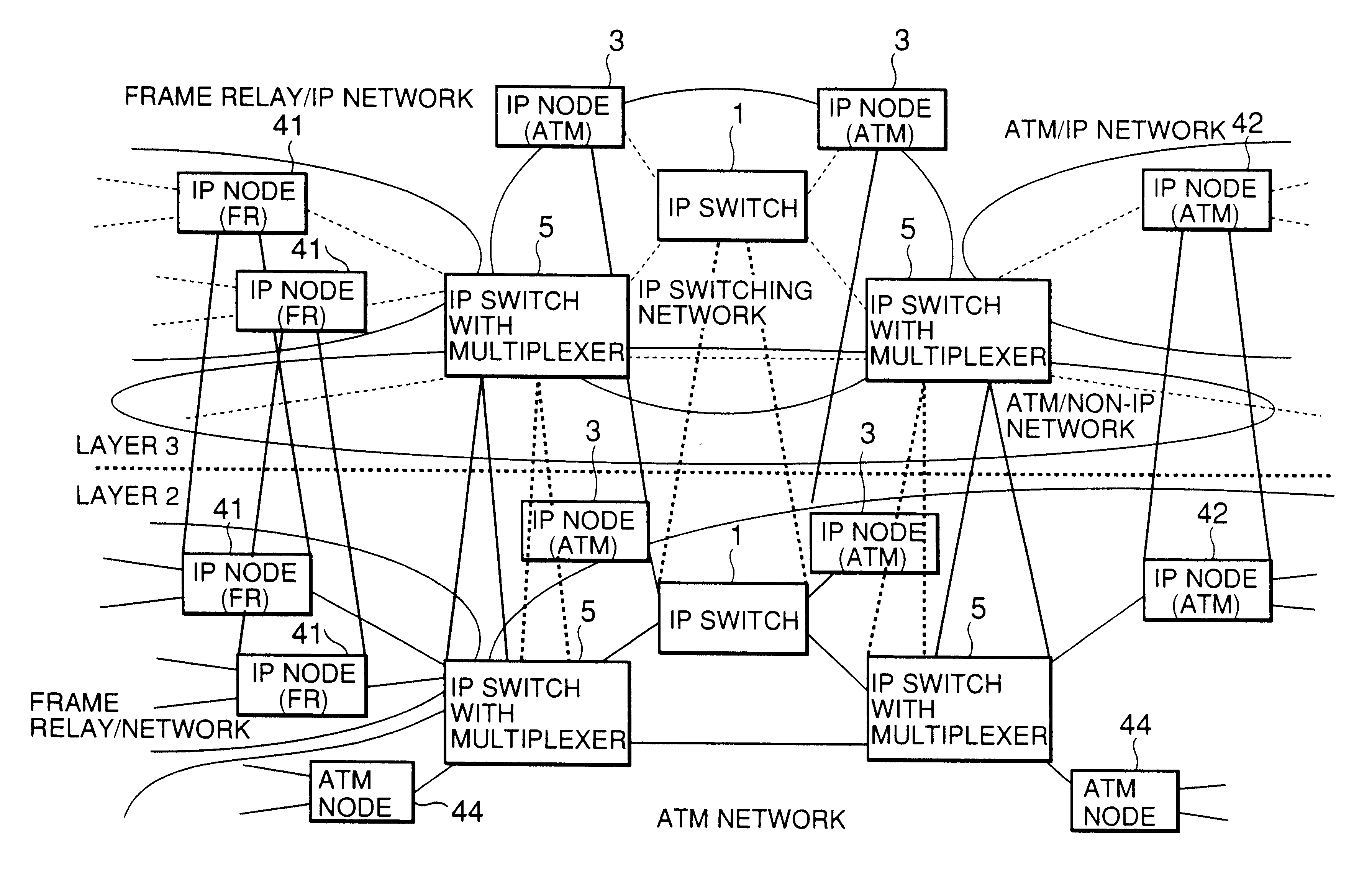
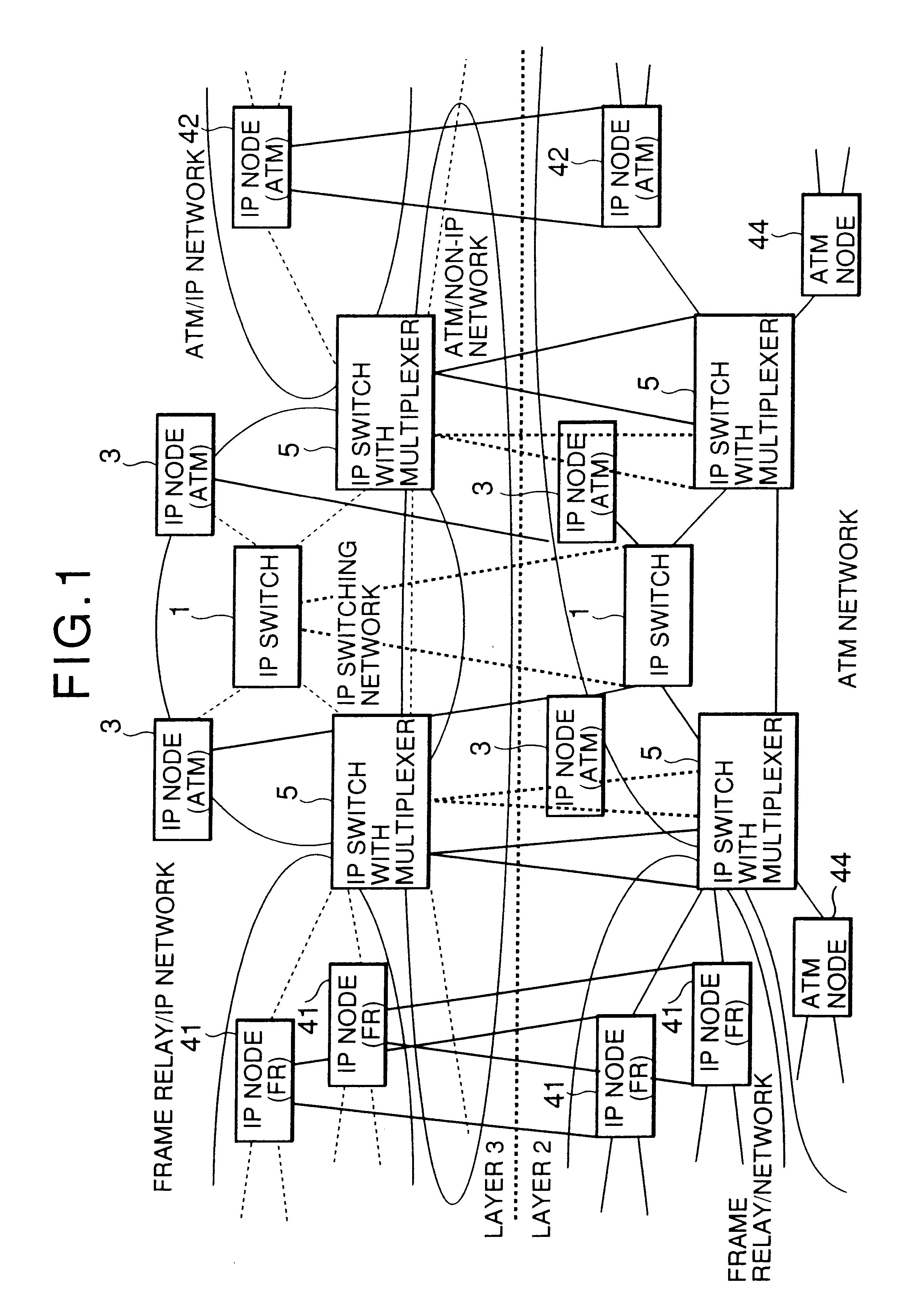
[0071]FIG. 1 shows an example of a network to which an IP switch with a multiplexer (a router apparatus using an ATM switch) according to an embodiment of the present invention is applied. In FIG. 1, the network is illustrated as being divided into logical layers, a layer 2 (subordinate layer) and a layer 3 (superordinate layer) as in the case of FIG. 48. The following description is directed to a case where IP (Internet Protocol) is used as a protocol of the layer 3. However, protocols of the layer 3 other than IP may be used.

[0072]In the network shown in FIG. 1 an IP switching network is constructed which connects a frame relay / IP network for transmitting IP packets on a frame relay and an ATM / IP network for transmitting IP packets on ATM. Since even an ATM / non-IP network for transmitting traffic other than IP by ATM can be connected to the IP swit...


PUM


Abstract

A router apparatus 5 is provided with an ATM switch, an IP controller for performing routing control as a controller for layer 3, plural kinds of interfaces which are individually provided to plural transmission paths in which various communications are performed, and a cell multiplexing / demultiplexing unit, and manages the cell communications between respective parts on the basis of identification information. The input packet is subjected to IP processing in an interface to be converted to a cell in a common format, and the cell is serially multiplexed with a cell from another interface on a cell basis, and transmitted to the ATM switch at the cell multiplexing / demultiplexing unit. Each interface and each cell multiplexing / demultiplexing unit sets and switches the identification information for the header portion of the packet and the cell to be communicated by using a table in which the corresponding relationship of the identification information is registered.

Description

[0001]The present application is a continuation of application Ser. No. 09 / 498,353, filed Feb. 4, 2000 now U.S. Pat. No. 6,424,662; which is a continuation of application Ser. No. 09 / 028,830, filed Feb. 13, 1998, now U.S. Pat. No. 6,046,999, which is a continuation-in-part application Ser. No. 08 / 923,873, filed Sep. 2, 1997, now U.S. Pat. No. 5,963,555 and is related to application Ser. No. 09 / 410,562, filed Oct. 1, 1999, now U.S. Pat. No. 6,512,745, the contents of which are incorporated herein by reference.BACKGROUND OF THE INVENTION[0002]1. Field of the Invention[0003]The present invention relates to a router apparatus which switches packets entailing the processing of a packet switching type layer 3 like IP (Internet Protocol), etc., by using an ATM (Asynchronous Transfer Mode, and particularly to a router apparatus for multiplexing plurality transmission paths for one physical port of the ATM switch.[0004]2. Description of the Related Art[0005]An IP (Internet Protocol) switchin...

Claims


Application Information

Patent Timeline
Patent Type & Authority Patents(United States)
IPC IPC(8): H04J3/04H04L12/28H04L12/56H04L12/66
CPCH04L12/5601H04L49/25H04L49/3072H04L49/602H04L49/606H04L2012/5667H04L2012/567
Inventor MIKI, KAZUHOTAKATORI, MASAHIROTAKASE, AKIHIKOMURAKAMI, MASARUWAKAYAMA, KOJIYOSHIMOTO, TETSUROKUNIMOTO, MASAO
Owner HITACHI LTD
Why Eureka
Try Eureka