Intergrated reservoir optimization

a reservoir optimization and integrated technology, applied in the field of integrated reservoir optimization, can solve problems such as insufficient publications in relation to the reservoir

Inactive Publication Date: 2005-12-27
SCHLUMBERGER TECH CORP
View PDF25 Cites 489 Cited by
  • Summary
  • Abstract
  • Description
  • Claims
  • Application Information

AI Technical Summary

Benefits of technology

[0037]It is a further object of the present invention to disclose a method of managing a fluid and / or gas reservoir, where the generating step (b2) for generating a production and reserves forecast in response to the numerical model studies or the analytical model studies includes: (b2.1) in response to a plurality of constraints and to the first output signal from the numerical model studies step which includes the history calibrated model, running a model in a simulator (the simulator production and reserves forecast) and generating a production forecast representing the way a reservoir responds to a development plan, said development plan defining a mechanism representing a process that is active in the reservoir field, (b2.2) determining whether an implementation plan of the mechanism or whether the constraints can be changed or optimized, (b2.3) if the implementation plan or the constraints can be changed or optimized, changing the implementation plan of the mechanism or the constraints, re-running the model in the simulator, and generating another production forecast, (b2.4) if the implementation plan or the constraints cannot be changed or optimized, determining if the mechanism representing the process that is active in the reservoir field can be changed, (b2.5) if the mechanism can be changed which represents a new development plan or new mechanism, revising an implementation plan of the new mechanism to create a new implementation plan and re-running the model in the simulator thereby generating still another production forecast, (b2.6) if the new implementation plan or the constraints cannot be changed or optimized and if the new mechanism cannot be changed, determine if there is any need for parametric sensitivity runs, (b2.7) if there is a need for parametric sensitivity runs, identify a set of uncertainties, alter a reservoir description in the history calibrated model, and repeat steps (b2.1) to (b2.5), (b2.8) if there is no need for any parametric sensitivity runs, generating a third output signal which includes reservoir fluids production rates and pressures and total fluids injection rates and pressures for the facilities requirements step (b3) and a reservoir development plan for the economics and risk analysis step (b5), the facilities requirements step (b3) responding to that third output signal; (b2.9) in response to the plurality of constraints and the second output signal from the analytical model studies step which includes the current well forecasts of production and reserves, the enhanced well production forecasts, and the infill forecasts of production and reserves, performing, in the analytical production and reserves forecast, analytical modeling and, responsive thereto, generating an analytical forecast for a particular mechanism and a particular set of development constraints, and (b2.10) repeating steps (b2.2) through b(2.8) until there is no need for any parametric sensitivity runs and generating a fourth output signal which includes reservoir fluids production rates and pressures and total fluids injection rates and pressures for the facilities requirements step (b3) and a reservoir development plan for the economics and risk analysis step (b5), the facilities requirements step (b3) responding to that fourth output signal.

Problems solved by technology

The methods disclosed in the cited Satter reference (reference 17 in the References section set forth below) and related publications are not entirely adequate because such methods fail to assimilate all of these ‘different types of data’.

Method used


Image

  • Intergrated reservoir optimization
  • Intergrated reservoir optimization
  • Intergrated reservoir optimization

Examples


Embodiment Construction

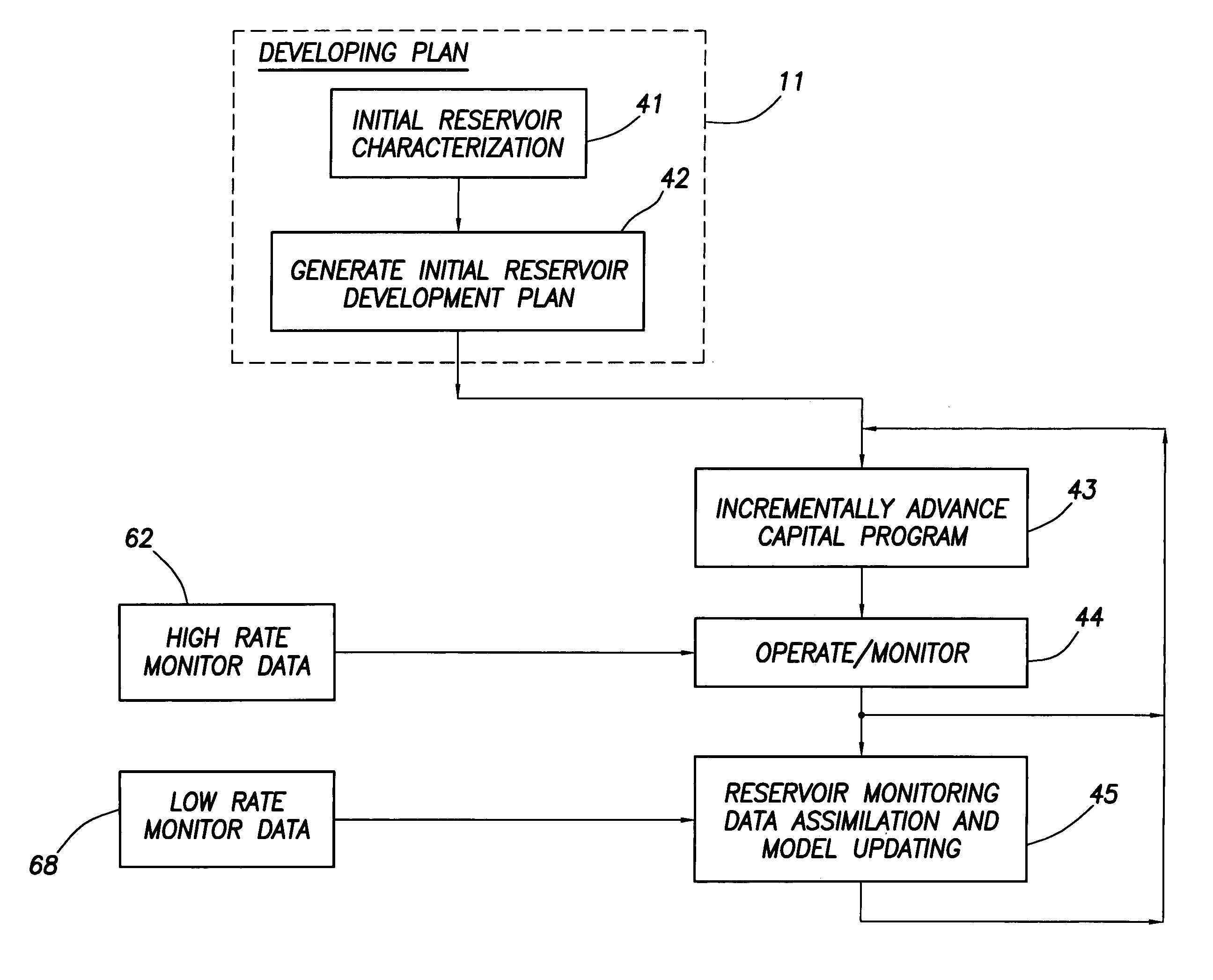
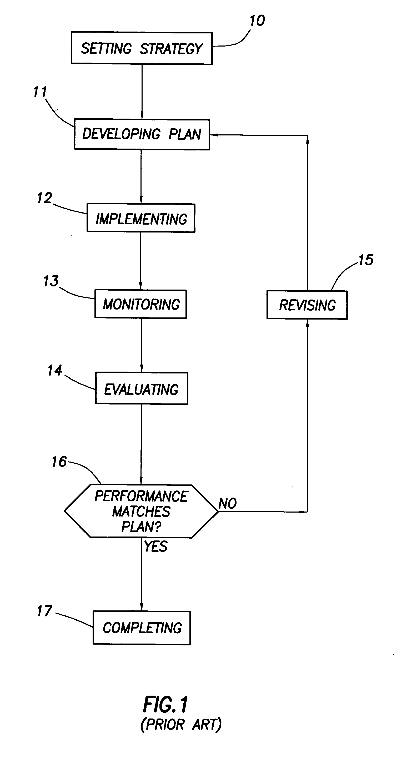
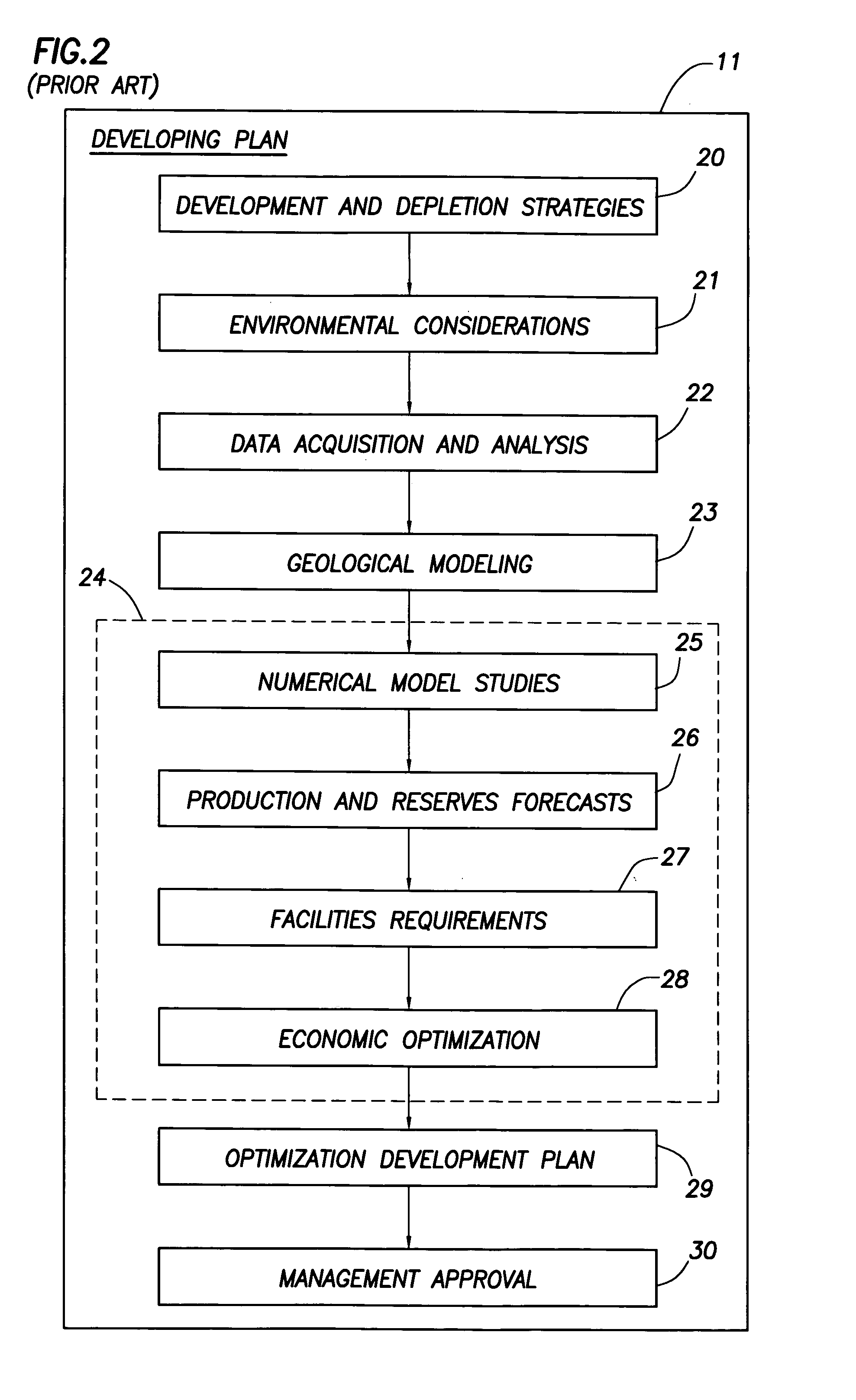
[0062]Referring to FIG. 1, one prior art method for managing a gas or oil reservoir (as taught in the Satter and Thakur book cited in the References section below) is illustrated. FIG. 1 shows a sequence of key steps comprising reservoir management. These steps consist of: setting strategy 10, Developing Plan 11, Implementing 12, Monitoring 13, Evaluating 14, Performance matches plan 16, Revising 15, and Completing 17. Each of these steps or block of FIG. 1 will be discussed in detail below.

Setting Strategy, Block 10

[0063]In FIG. 1, the process begins with the Setting Strategy step in block 10 wherein short-term and long-term strategies or goals for managing the reservoir are set. This includes reviewing: the key elements of reservoir characteristics as is generally determined from seismic logging information, the total environment of the reservoir, and the available technology for developing the reservoir. Although one may not have a fixed strategy, one may nevertheless have severa...


PUM


Abstract

A method of managing a fluid or gas reservoir is disclosed which assimilates diverse data having different acquisition time scales and spatial scales of coverage for iteratively producing a reservoir development plan that is used for optimizing an overall performance of a reservoir. The method includes: (a) generating an initial reservoir characterization, (b) from the initial reservoir characterization, generating an initial reservoir development plan, (c) when the reservoir development plan is generated, incrementally advancing and generating a capital spending program, (d) when the capital spending program is generated, monitoring a performance of the reservoir by acquiring high rate monitor data from a first set of data measurements taken in the reservoir and using the high rate monitor data to perform well-regional and field-reservoir evaluations, (e) further monitoring the performance of the reservoir by acquiring low rate monitor data from a second set of data measurements taken in the reservoir, (f) assimilating together the high rate monitor data and the low rate monitor data, (g) from the high rate monitor data and the low rate monitor data, determining when it is necessary to update the initial reservoir development plan to produce a newly updated reservoir development plan, (h) when necessary, updating the initial reservoir development plan to produce the newly updated reservoir development plan, and (i) when the newly updated reservoir development plan is produced, repeating steps (c) through (h). A detailed disclosure is provided herein relating to the step (a) for generating the initial reservoir characterization and the step (b) for generating the initial reservoir development plan.

Description

CROSS REFERENCE TO RELATED APPLICATIONS[0001]This is a Utility Application of prior Provisional Application Ser. No. 60 / 183,836 filed Feb. 22, 2000 entitled “Method for monitoring and controlling drainage of a petroleum reservoir”.BACKGROUND OF THE INVENTION[0002]The invention relates to a method known as “Integrated Reservoir Optimization” (IRO) which includes a method for monitoring and controlling the extraction of fluid and gas deposits from subsurface geological formations. This includes a method for monitoring the status of fluid and gas deposits in subsurface geological formations and controlling the location and use of physical resources and extraction rates to maximize the extraction of such deposits from the subsurface geological formations.[0003]During the production life cycle of oil and gas extracted from reservoir fields in geological formations, certain stages are followed which include exploration, appraisal, reservoir development, production decline, and abandonment...

Claims


Application Information

Patent Timeline
Patent Type & Authority Patents(United States)
IPC IPC(8): E21B41/00E21B43/00E21B49/00G01V11/00G06F19/00G06Q10/06G06Q50/02
CPCE21B43/00E21B49/00G06Q10/06G01V11/00G01V2210/612Y02P90/84G06Q50/02
Inventor GURPINAR, OMER M.ROSSI, DAVID J.VERMA, VIDYA B.PANTELLA, PHILIP W.
Owner SCHLUMBERGER TECH CORP
Why Eureka
Try Eureka