Turbocharged internal combustion engine with EGR flow

a technology of internal combustion engine and turbocharger, which is applied in the direction of machines/engines, mechanical equipment, non-fuel substance addition to fuel, etc., can solve the problems of affecting fuel economy, setting the exhaust manifold pressure higher than the intake manifold pressure,

Inactive Publication Date: 2006-01-03
DETROIT DIESEL CORP
View PDF15 Cites 61 Cited by
  • Summary
  • Abstract
  • Description
  • Claims
  • Application Information

AI Technical Summary

Problems solved by technology

The problem is that with the intake manifold at a higher pressure than the exhaust manifold, exhaust gases cannot flow into the intake manifold for EGR.
Setting the exhaust manifold pressure higher than intake manifold pressure is bad for fuel economy.

Method used


Image

  • Turbocharged internal combustion engine with EGR flow
  • Turbocharged internal combustion engine with EGR flow

Examples


Embodiment Construction

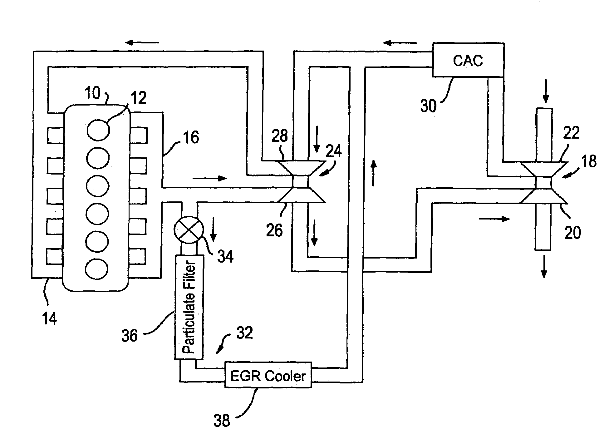
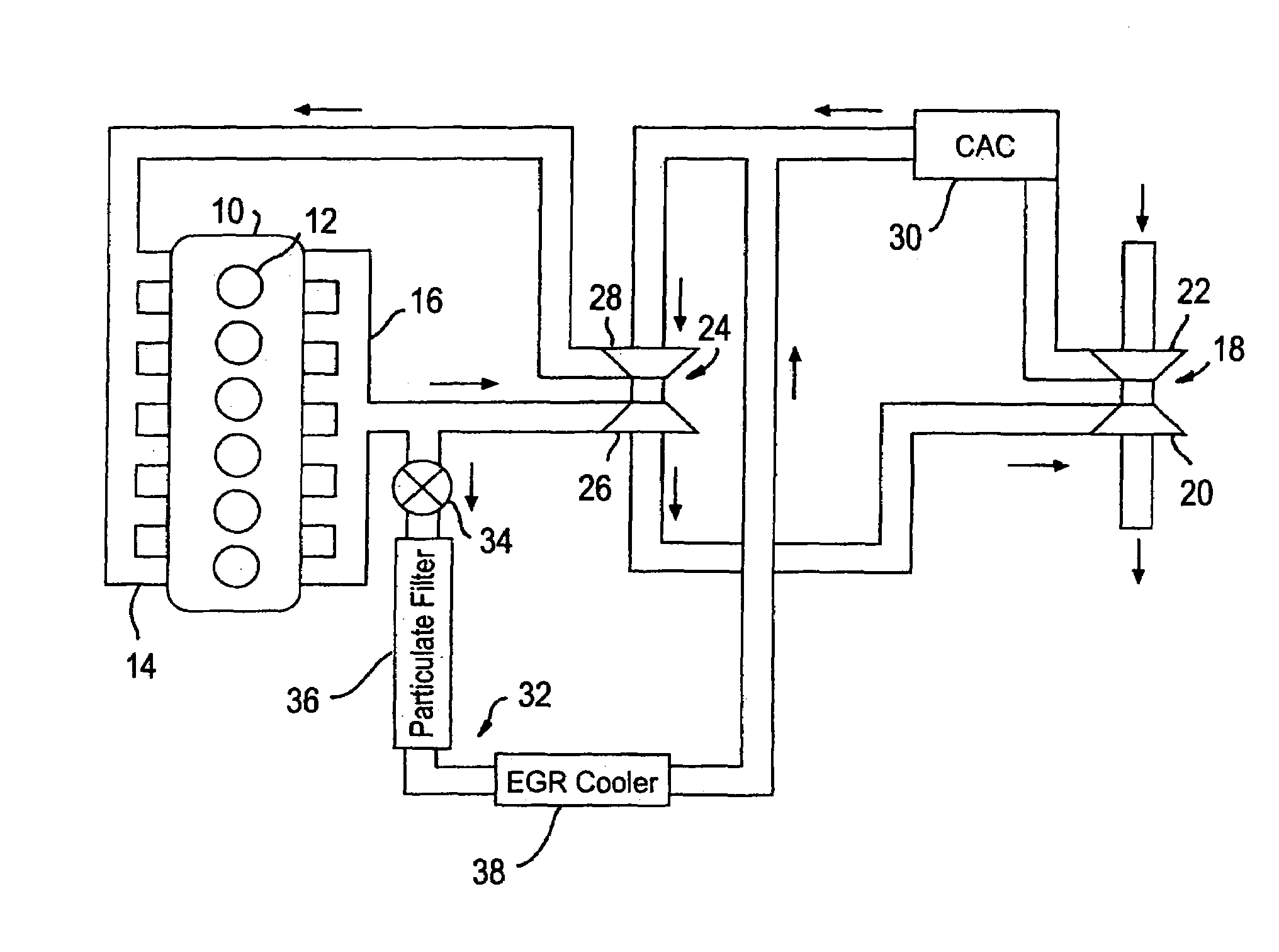
[0018]An internal combustion engine includes an engine block 10 with a plurality of cylinders 12. The illustrated engine is a compression-ignition internal combustion engine such as a heavy-duty diesel fuel engine. Cylinders 12 receive pressurized fuel from a fuel supply in a known manner. The engine includes an intake manifold 14 and an exhaust manifold 16. The engine is a turbocharged engine and is operated such that the intake manifold pressure generally exceeds the exhaust manifold pressure. The air system is configured with two turbochargers. A low pressure turbocharger 18 includes a turbine 20 driven by the exhaust gases and a compressor 22. Compressor 22 has an inlet receiving fresh intake air and an outlet providing low pressure charge air. A high pressure turbocharger 24 includes a turbine 26 driven by the exhaust gases and a compressor 28. Compressor 28 has an inlet receiving the low pressure charge air from low pressure turbocharger 18 and an outlet providing high pressur...


PUM


Abstract

A turbocharged internal combustion engine is operated such that the intake manifold pressure generally exceeds the exhaust manifold pressure. A low pressure turbocharger and a high pressure turbocharger are provided in series. An exhaust gas recirculation (EGR) system passively routes a portion of the exhaust gases to the high pressure turbocharger compressor inlet.

Description

STATEMENT REGARDING FEDERALLY SPONSORED RESEARCH OR DEVELOPMENT[0001]This invention was made with Government support under Contract No. DE-FC05-00OR22805. The Government has certain rights to the invention.BACKGROUND OF THE INVENTION[0002]1. Field of the Invention[0003]The present invention relates to a turbocharged internal combustion engine that includes an exhaust gas recirculation (EGR) system.[0004]2. Background Art[0005]The heavy-duty engine business is extremely competitive. Increasing demands are being placed on engine manufacturers to design and build engines that provide better engine performance, improved reliability, and greater durability while meeting more stringent emission and noise requirements. One approach to meet more stringent emission requirements is to utilize an exhaust gas recirculation (EGR) system.[0006]On a conventional turbocharged diesel engine, the intake manifold is at a higher pressure than the exhaust manifold. This relationship results in the best ...

Claims


Application Information

Patent Timeline
Patent Type & Authority Patents(United States)
IPC IPC(8): F01N3/02F02M25/06F02B37/00F01N3/021F02B37/013F02B37/02F02D21/08F02M25/07
CPCF02B37/013F02M25/0711F02B37/004F02M25/074F01N3/021F02M25/0719Y02T10/121Y02T10/144F02M25/0727F02M26/08F02M26/16F02M26/23F02M26/35Y02T10/12
Inventor SISKEN, KEVIN DEANBOLTON, BRIAN KENNETH
Owner DETROIT DIESEL CORP
Why Eureka
Try Eureka