
Grenade dispense mechanism for non-spin dual purpose improved conventional munitions

Inactive Publication Date: 2006-01-03
ARMY US SEC THE
View PDF8 Cites 13 Cited by
  • Summary
  • Abstract
  • Description
  • Claims
  • Application Information

AI Technical Summary

Benefits of technology

[0029]Specifically dual purpose conventional munitions (DPICM) depend on high rates of spin of stabilized artillery projectiles to expel and dispense their grenade payloads over a large target area. These projectiles obtain their high rates of spin during gun launch. As the projectile travels down the gun tube, the projectile rotating band engages the lands and grooves of the rifled gun tube imparting a twisting action or torque to the projectile. The projectile emerges from the gun tube with high spin and velocity. The projectile flies a ballistic trajectory toward the target zone many kilometers down range. At a pre-determined point along the trajectory, the projectile time fuze, which is set at the gun, functions to provide initiation output to the payload expulsion charge assembly. The assembly contains a propellant which when ignited, produces a gas pressure acting on a pusher plate or piston. The gas pressure increases with time (msec) until the forces of the gas pressure acting on the pusher plate through the grenade payload to the base / tail assembly are sufficient to shear the thread attachment of the base assembly to the projectile body section. Upon thread shear, the base separates from the projectile body permitting the movement of the grenade payload toward the aft open end of the projectile body. The grenades emerge from the projectile body with rotational and tangential velocity determined by their position in the payload section. This rotational and translational velocity causes the grenades to disperse, arm and stabilize to form a large, approximately uniform, distribution of grenades in a pattern effects area over the target.

Problems solved by technology

These projectiles obtain their high rates of spin during gun launch.

Method used


Image

  • Grenade dispense mechanism for non-spin dual purpose improved conventional munitions
  • Grenade dispense mechanism for non-spin dual purpose improved conventional munitions
  • Grenade dispense mechanism for non-spin dual purpose improved conventional munitions

Examples


Embodiment Construction

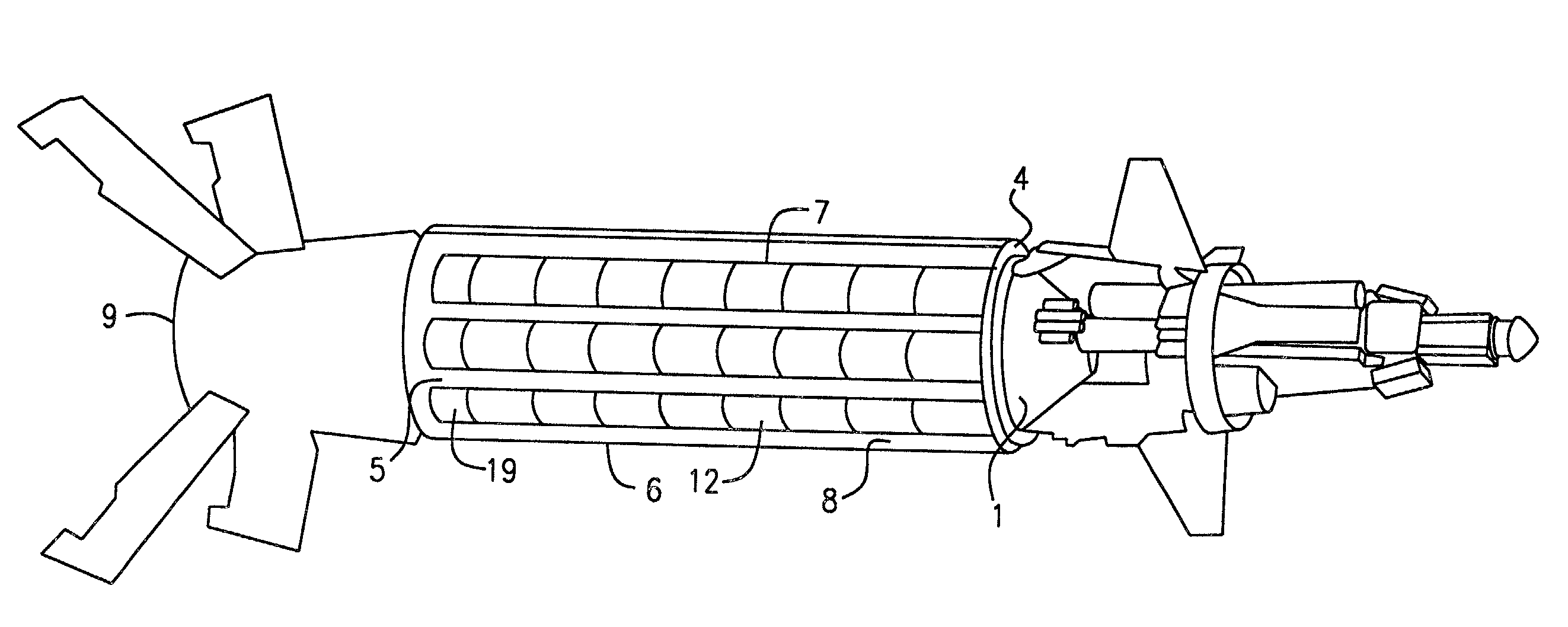
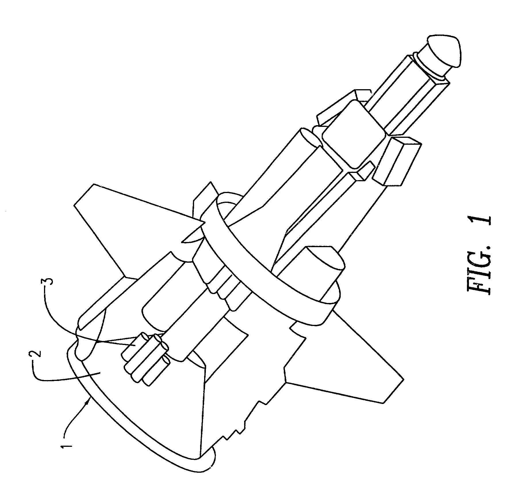
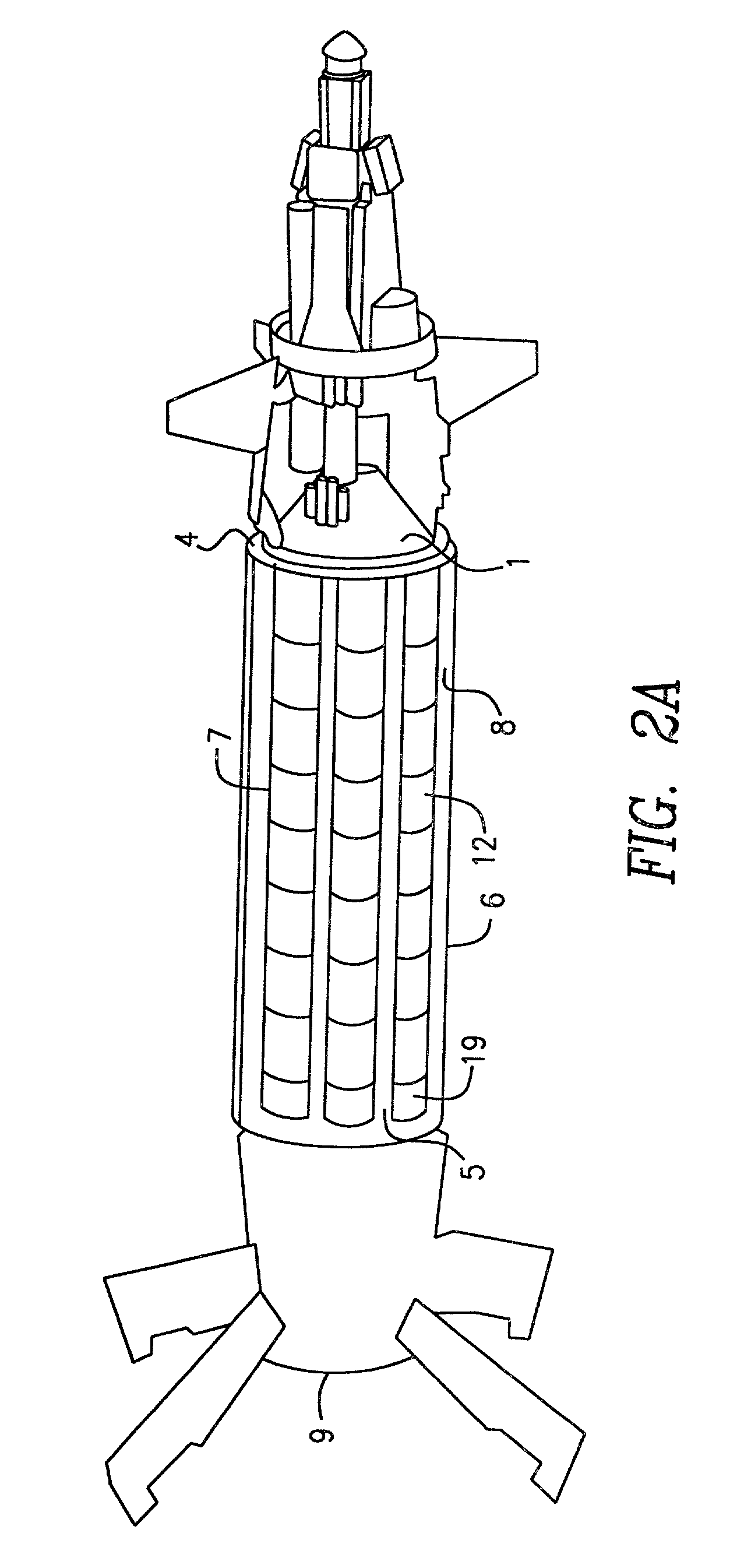
[0047]Grenade dispense mechanism for non-spin dual purpose improved conventional munitions according to the first embodiment of the present invention is depicted in FIGS. 1–7. With particular reference to FIGS. 1 and 2, the expulsion charge assembly 1 located toward the forward ogival end of the carrier, consists of a container with a quantity of ignitable propellant charge 2 such as M10, ball powder or other comparable propellants. The expulsion charge 2 is ignited by the action of the primary projectile fuze 3 at a predetermined point near or at the target area. The expulsion charge 2 at FIG. 1 produces a gas pressure whose build up in time (msecs) exerts a force on the pusher plate 4 at FIG. 2 located adjacent to the expulsion charge 2 to separate the base end 5 of the projectile 6 to cause the payload canister 7 at FIG. 2A to move rear-ward in the payload section 8 of FIG. 2A.

[0048]More particularly, FIG. 2A and FIG. 7C show the pusher plate 4 which acts as a piston to transmit ...


PUM


Abstract

A grenade dispensing mechanism for non-spin or low spin dual purpose improved conventional munition launched from inside a projectile. At a pre-determined point along the trajectory, the projectile time fuze which is set at the gun functions to provide initiation output to the payload expulsion charge assembly. The payload expulsion charge assembly contains a propellant which when ignited, produces a gas pressure acting on a pusher plate which acts as a piston. The gas pressure increases with time until the forces of the gas pressure acting on the pusher plate through the grenade payload to the base / tail assembly are sufficient to shear the thread attachment of the base assembly to the projectile body section. An obturator band serves to seal the expulsion gas pressures to prevent excessive gas blow-by as the payload canister assembly travels through the rifled projectile body section. Upon thread shear, the base separates from the projectile body permitting movement of the grenade payload toward the aft open end of the projectile body. The projectile payload section is in the warhead / payload canister assembly. A pre-engraved rotating band attached to the payload canister as it travels through the projectile section rifling creates a torque thus the grenades emerge from the projectile body with rotational and tangential velocity determined by their position in the payload section which cause the grenades to disperse, arm and stabilize to form a large approximately uniform, distribution of grenades in a pattern effects over a target area.

Description

U.S. GOVERNMENT INTEREST[0001]The invention described herein may be manufactured, used or licensed by or for the U.S. Government, for U.S. Government purposes.BACKGROUND OF INVENTION[0002]I. Field of Invention[0003]This invention applies to the field of artillery projectiles fired from gun platforms and launchers that are known as dual purpose conventional munitions.[0004]II. Background of the Invention[0005]Dual purpose conventional munitions (DPICM) have historically been developed for high spin gun fired artillery projectiles. The changing requirements of the military to achieve longer ranges have dictated the pursuit of fin stabilized guidance projectile warheads with non-spin / low spin characteristics. Projectiles such as the XM 982 and EX-171 extended range DPICM pose unique problems, which require solutions. These are:[0006]a. Grenade fuze arming.[0007]b. Grenade stabilization / orientation.[0008]c. Grenade dispersion for ground pattern effects size and distribution.[0009]d. Nee...

Claims


Application Information

Patent Timeline
IPC IPC(8): F42B12/60
CPCF42B12/60
Inventor ADIMARI, LOUIS J.
Owner ARMY US SEC THE
Learn More