Method and apparatus for unloading ribbon rails from rail cars

a technology for unloading ribbon rails and rail cars, which is applied in the direction of transportation items, refuse gathering, and ways, etc., can solve the problems of increasing labor requirements, increasing the difficulty of laying track, and requiring a considerable amount of manual labor, so as to reduce the danger of personal injury and reduce labor requirements

Active Publication Date: 2006-01-03
HERZOG CONTRACTING
View PDF8 Cites 32 Cited by
  • Summary
  • Abstract
  • Description
  • Claims
  • Application Information

AI Technical Summary

Benefits of technology

[0010]The present invention is directed to an improved apparatus for unloading ribbon rails and also to an improved method by which the ribbon rails can be unloaded with reduced labor requirements and reduced danger of personal injury.
[0014]The present invention is advantageous in a number of respects, perhaps most notably because it creates substantial labor and cost savings and minimizes injury risk. There is no need to thread and connect and disconnect a winch cable and no need to attach and detach tie bars between successive ribbon rails. Additionally, the entire unloading process can be carried out more quickly than with prior equipment. Only two workers are required, one to operate the gantry crane and another to operate the thread boxes, and both are in a safe environment in cabs.

Problems solved by technology

In the railroad industry, one of the more difficult and labor intensive operations is the laying of track, either in new railway construction or in the replacement of worn or damaged existing rails.
As can easily be appreciated, this procedure requires a considerable amount of manual labor.
The workers also have to cover great distances to detach the tie bars each time a pair of rails has been unloaded.
Perhaps even more disadvantageous than the labor costs is the risk of serious injury that is encountered due to the need for extensive manual handling of the rails, the winch cable, the tie bars and other associated equipment.
The guide rollers do not provide power assistance for either loading or unloading of rails, and the crane is used to perform essentially the same work as the winch which is used in the conventional unloading procedure previously described.
Consequently, if this type of equipment is used in the unloading of rails, the rails still have to be tied end to end manually using tie bars, and the high labor costs and the high risk of personal injury remain serious problems.

Method used


Image

  • Method and apparatus for unloading ribbon rails from rail cars
  • Method and apparatus for unloading ribbon rails from rail cars
  • Method and apparatus for unloading ribbon rails from rail cars

Examples


Embodiment Construction

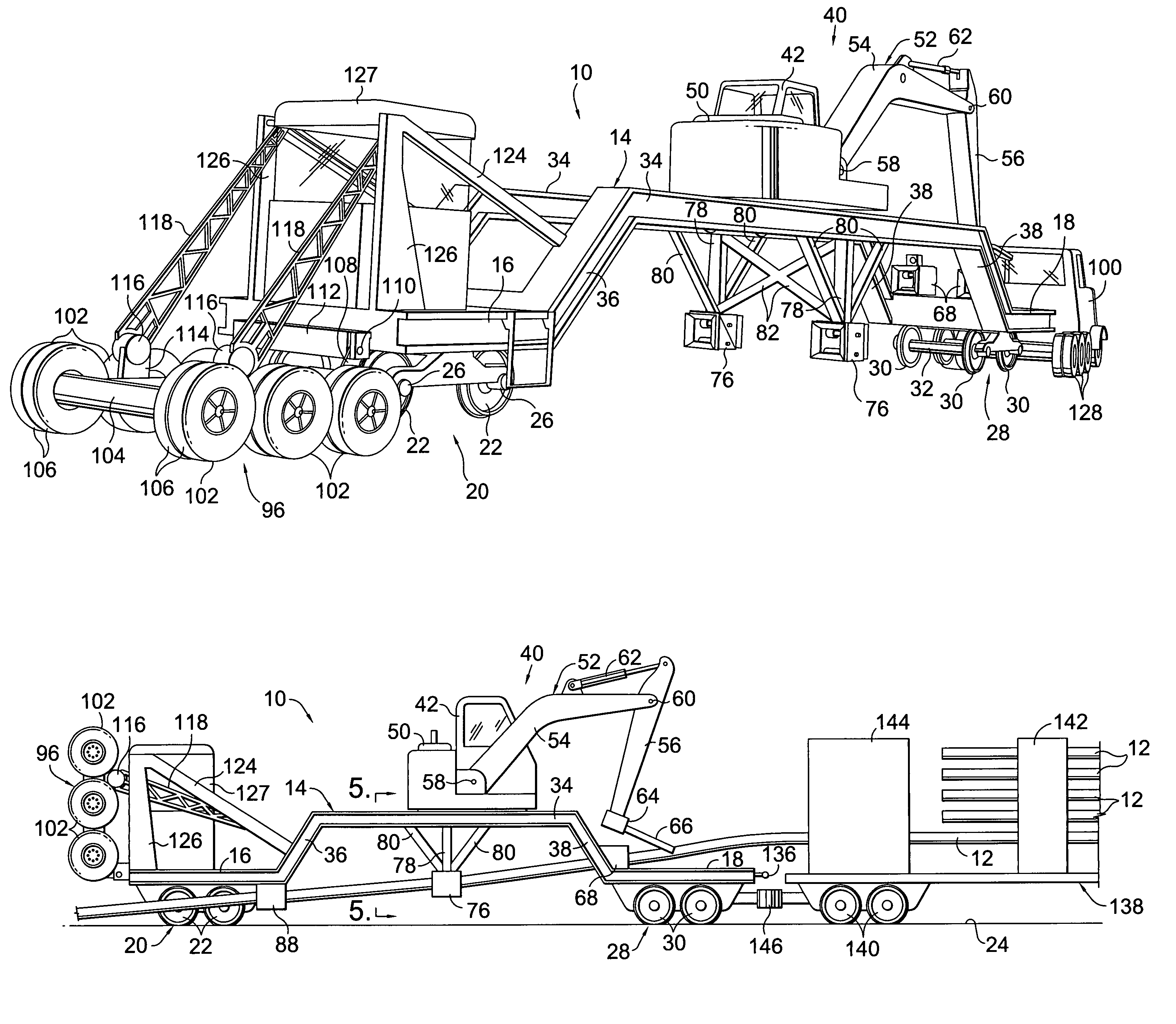
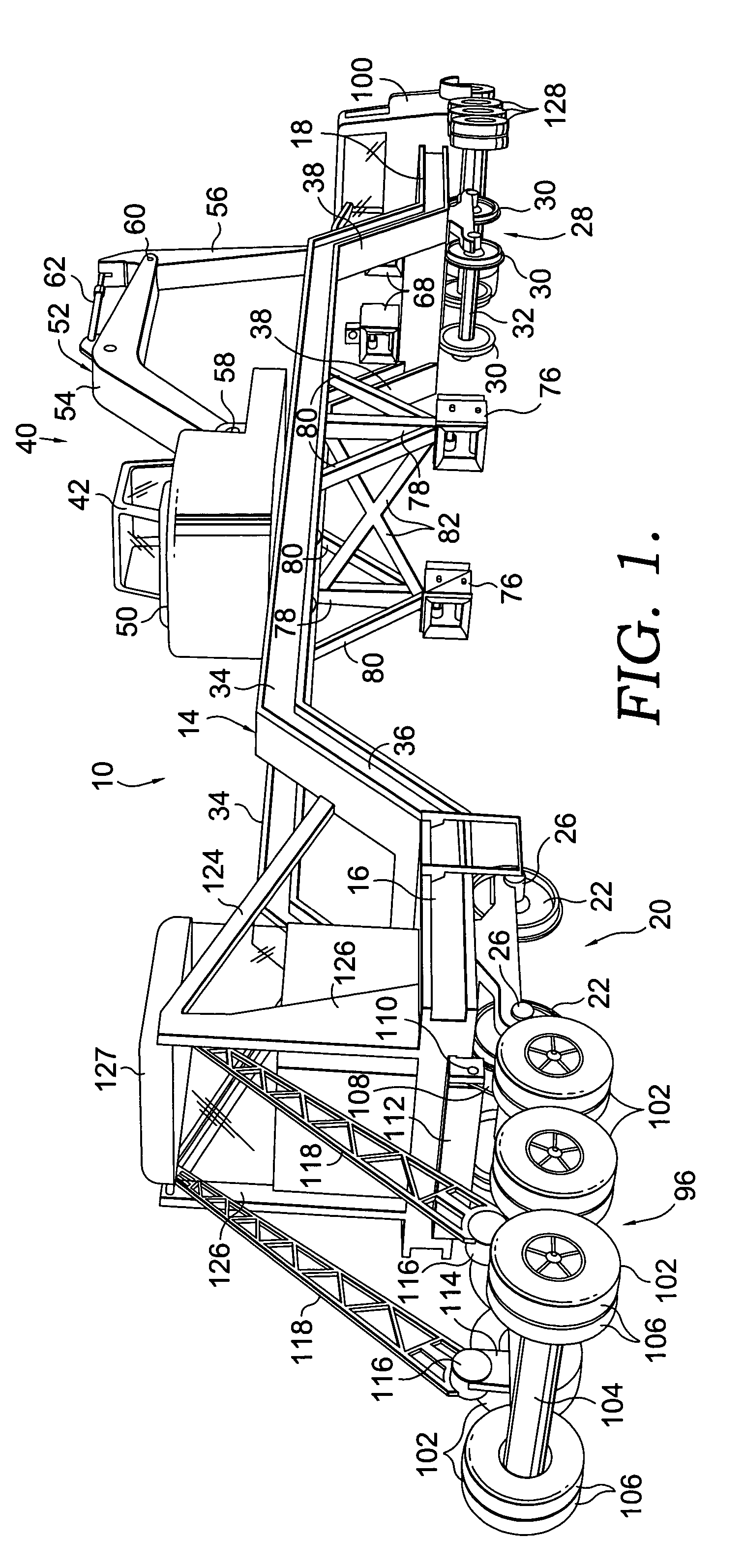
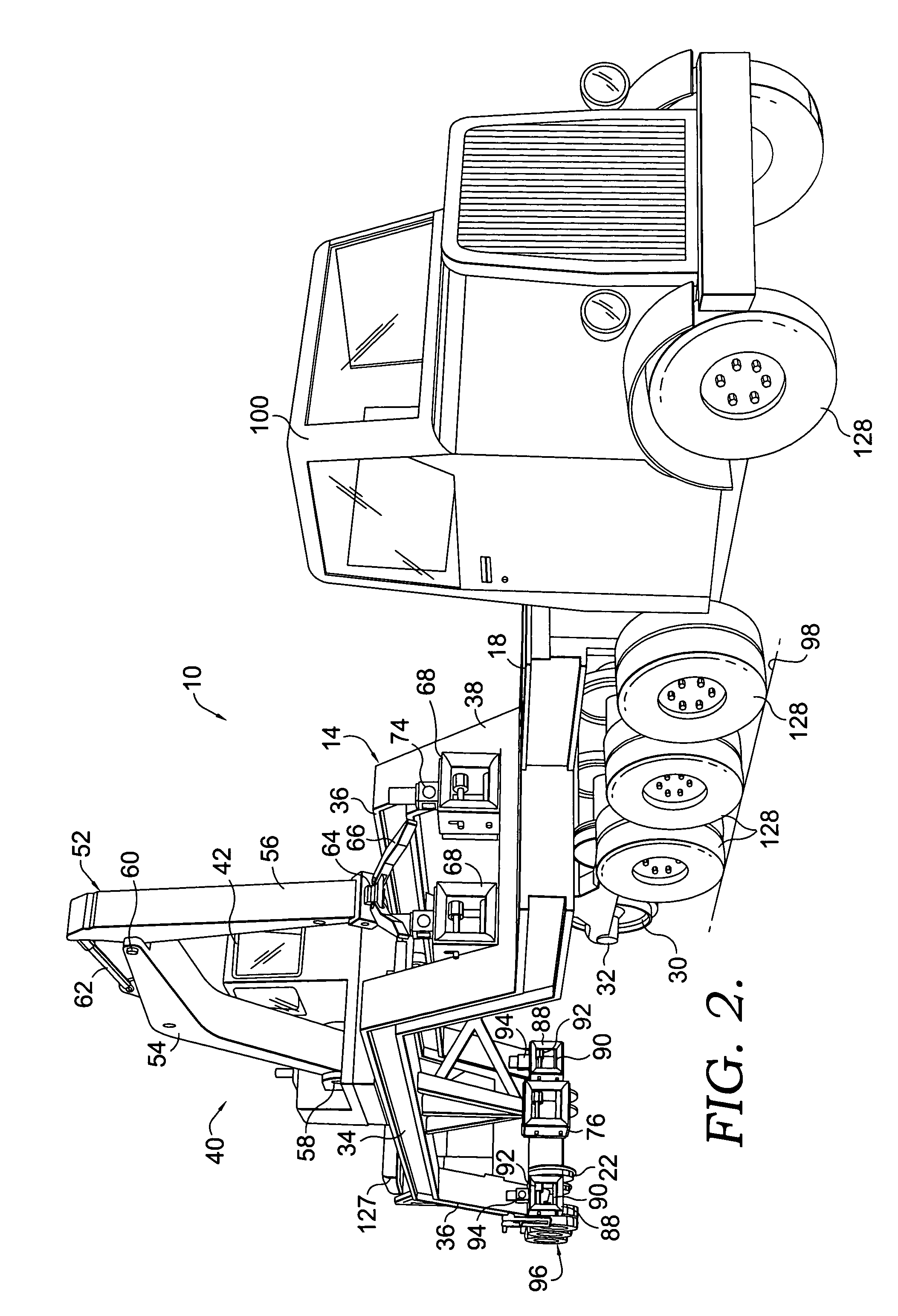
[0023]Referring now the drawings in more detail, numeral 10 generally designates a specially constructed rail car which is used for the unloading of elongated ties such as the ribbon ties 12 which are shown in FIG. 3 and which are formed by welding rail sections together end to end. The ribbon ties 12 may each have a length up to 1800 feet or more.

[0024]The rail car 10 has a rigid frame which is generally designated by numeral 14 and which includes on its back end a generally horizontal platform 16 and on its front end a generally horizontal platform 18. The rear platform 16 is equipped with a pair of flanged wheel assemblies 20 each of which includes a pair of flanged wheels 22 for application to a railroad track 24. The wheels 22 on opposite sides of the frame are mounted on axles 26. The front platform 18 is similarly mounted on a pair of front wheel assemblies 28 each including a pair of flanged wheels 30. The wheels 30 on opposite sides of the frame are mounted on axles 32. The...


PUM


Abstract

A method and apparatus for unloading long ribbon rails which are carried on a transport car on bunks which hold the rails in four or five different tiers each containing eight to ten rails. A special railcar is equipped with a gantry crane which feeds the rails from the bunks into power driven thread boxes. The thread boxes grip the rails and feed them rearwardly onto the railway bed. After the first two rails have been unloaded side by side, the next pair are fed into the thread boxes. The thread boxes feed these rails out of the bunks as the train is moved forwardly at the same speed as the rails are fed rearwardly so that the rails are unloaded end to end with the first pair of rails. The railcar has retractable over the road wheels that allow it to be towed on the roadway to the site of the rail transport car.

Description

CROSS-REFERENCE TO RELATED APPLICATIONS[0001]Not applicable.STATEMENT REGARDING FEDERALLY SPONSORED RESEARCH OR DEVELOPMENT[0002]Not applicable.FIELD OF THE INVENTION[0003]This invention relates generally to railroad equipment and more particularly to a method and apparatus for unloading long rails that are commonly referred to in the industry as ribbon rails.BACKGROUND OF THE INVENTION[0004]In the railroad industry, one of the more difficult and labor intensive operations is the laying of track, either in new railway construction or in the replacement of worn or damaged existing rails. It is an industry standard for rails to be manufactured in sections that are each 39 feet long. In order the maximize quality control and minimize costs, the sections are often welded together end to end at a steel mill to form longer sections that are commonly known as ribbon rails. These ribbon rails can be any length up to 1800 feet long or even longer.[0005]Ribbon rails are transported to the are...

Claims


Application Information

Patent Timeline
Patent Type & Authority Patents(United States)
IPC IPC(8): B65G13/00E01B1/00E01B29/17
CPCE01B29/17
Inventor HERZOG, STANLEY M.BOUNDS, IVAN E.BEERS, TIMOTHY M.GLADDEN, WAYNE LEEGUERRA, LAWRENCE E.
Owner HERZOG CONTRACTING
Why Eureka
Try Eureka