Curing formation equipment of positive temperature coefficient (PTC) heating device

A heating device, curing molding technology, applied in the direction of ohmic resistance heating parts, electric heating devices, electrical components, etc., can solve problems such as loose aluminum tube heating elements, large power consumption, and non-parallel sides of the product

Active Publication Date: 2017-11-24
WUXI GUOWEI CERAMIC ELECTRICAL APPLIANCES CO LTD
View PDF6 Cites 16 Cited by
  • Summary
  • Abstract
  • Description
  • Claims
  • Application Information

AI Technical Summary

Problems solved by technology

[0005] The efficiency of the above process or technology is low, the power consumption is large during the curing process, and the consistency of the product is poor. It is unavoidable to avoid the occurrence of unqualified products due to human operation errors and the unqualified rate is also high. After curing, it is necessary to conduct power-on or high-voltage tests.
In particular, manually aligning the head and end of the heating element will inevitably lead to errors that cause the two sides of the product to be non-parallel, and the process of knocking out the corrugated h...

Method used


Image

  • Curing formation equipment of positive temperature coefficient (PTC) heating device
  • Curing formation equipment of positive temperature coefficient (PTC) heating device
  • Curing formation equipment of positive temperature coefficient (PTC) heating device

Examples


Embodiment 1

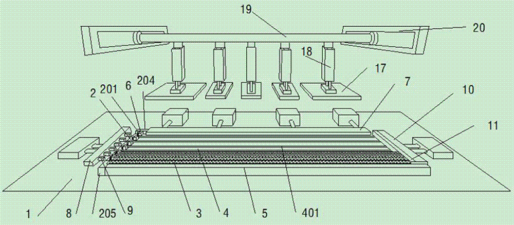
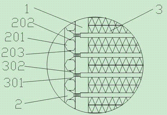
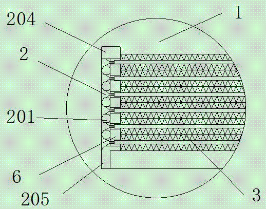
[0049] Such as Figure 1~3 The solidification molding equipment of a kind of PTC heating element shown, comprises console 1, and described console one end is fixed with circuit board 2, and described circuit board 2 is provided with several No. 1 fixing blocks 201 alternately, and No. 1 fixing blocks 201 The two sides are respectively provided with a positive electrode head 202 and a negative electrode head 203, and the PTC heating element 3 is arranged on the console 1, and the positive electrode sheet 301 and the negative electrode sheet 302 of the electrode lead-out end of the PTC heating element 3 are connected to the positive electrode head 202 and the negative electrode head respectively. 203 connection, there is a groove 4 corresponding to the PTC heating device 3 on the operating table 1, and the width of the groove 4 is greater than or equal to the width of the heating element of the heating device.

[0050] Further, the groove 4 has a convex strip 401 in the middle. ...

Embodiment 2

[0060] Such as figure 1The non-leading tail end surface positioning device of the solidification molding equipment of a PTC heating device as shown includes an operation table 1, a circuit board 2 is fixed at one end of the operation table, and a PTC heating device 3 is arranged on the operation table 1, and the PTC heating device 3 A current loop is formed with the circuit board 2, and the positioning device includes a No. 3 push plate 10, which pushes and positions the end of the PTC heating element 3 in the width direction through the No. 3 push plate 10. The positioning device is arranged at one end of the console 1 .

[0061] Further, between the No. 3 push plate 10 and the end of the PTC heating element 3, there is an adjustment spacer 11 parallel to the No. 3 push plate 10 and the end of the PTC heating element 3. The adjustment spacer 11 is controlled and promoted by No. 3 push pedal 10 .

Embodiment 3

[0063] Such as Figure 8 The electrode lead-out positioning device of the solidification molding equipment of a PTC heating device as shown includes an operation table 1, a circuit board 2 is fixed at one end of the operation table, and a PTC heating device 3 is arranged on the operation table 1, and the PTC heating device 3 and The circuit board 2 forms a current loop, and the electrode lead-out positioning device includes a positioning baffle 12, the positioning baffle 12 is perpendicular to the console 1, and the positioning baffle 12 is connected to the PTC heating element 3 placed on the console 1 The lead-out end faces of the electrodes are parallel and close to each other, and there is a No. 2 groove 13 for accommodating and leading out the lead-out electrodes at the position corresponding to the lead-out electrodes of the heating element 3 at the wall thickness of the positioning baffle 12 .


PUM


Abstract

The invention discloses curing formation equipment of a positive temperature coefficient (PTC) heating device. The curing formation equipment comprises an operating table, wherein a circuit board is fixedly arranged at one end of the operating table, a time relay and an AC contactor also can be laid on the operating table, a plurality of first fixed blocks are arranged on the circuit board at intervals, a positive pole head and a negative pole head are respectively arranged at two sides of each first fixed block, the PTC heating devices are arranged on the operating table, and a positive pole plate and a negative pole plate at electrode leading-out end heads of each PTC heating device are respectively and tightly clamped by a positive pole head clamping device and a negative pole head clamping device. In the operating table, positioning and push devices are arranged at two ends in a length direction, a shaping press device is arranged on a tabletop, and a groove can be formed in the tabletop. Compared with the prior art, the curing formation equipment is simpler in structure, the consistency, the reliability and the stability of a product can be obviously improved, and an obvious invention and creative effect is also brought to aspects of improving production efficiency, reducing manual cost and improving product consistency.

Description

technical field [0001] The invention belongs to the field of electronic machinery, and in particular relates to curing molding equipment for PTC heating devices. Background technique [0002] PTC heating devices have the advantages of constant temperature heating, no open flame, high heat conversion rate, and little influence on power supply voltage, etc., and have been widely used in various electrical products. Chinese patent 200920230829.5 discloses a PTC electric heater. This heater consists of a heat-conducting aluminum tube, a cooling strip, and a heating element penetrated into the heat-conducting aluminum tube. The heating element is covered by a temperature-resistant insulating film and clamped Composed of PTC heating elements between the electrode sheets, between the PTC heating elements and the electrode sheets in the heating body and between the heating element and the heat dissipation strip, temperature-resistant and flame-retardant organic silica gel is require...

Claims


Application Information

Patent Timeline
IPC IPC(8): H05B3/00H05B3/02
CPCH05B3/00H05B3/02
Inventor 蒋国屏
Owner WUXI GUOWEI CERAMIC ELECTRICAL APPLIANCES CO LTD
Why Eureka
Try Eureka