Sewing machine

a sewing machine and thread technology, applied in the field of sewing machines, can solve the problems of insufficient handling of the thread guard or the needle eye, damage of the thread take-up lever or the thread tension regulator, and inability to smoothly pull out, so as to enhance the operation efficiency, simplify the connection of the thread with the thread take-up lever or the thread tension regulator, and improve the effect of operation efficiency

Inactive Publication Date: 2006-01-03
BROTHER KOGYO KK
View PDF15 Cites 6 Cited by
  • Summary
  • Abstract
  • Description
  • Claims
  • Application Information

AI Technical Summary

Benefits of technology

[0018]The movable controller is so disposed in the arm of the sewing machine as to be movable at least within the predetermined range. In case the needle thread is engaged in the former construction with at least one of said thread take-up lever or said thread tension regulator, the needle thread, as fed out from the thread bobbin by the operator, is pulled out at first along a predetermined needle thread passage (or a feed passage) to the position of the needle. In this case, the needle thread may be moved and engaged in a normal state with said thread take-up lever or said thread tension regulator by the subsequent moving control of said movable controller. Therefore, said needle thread may be arranged not only at a position where it can be instantly engaged along the needle thread passage with said thread take-up lever or said thread tension regulator but also in the vicinity of said thread tension regulator or at a position corresponding to the moving locus of the thread take-up lever. Moreover, the needle thread may also be arranged either at a distance from said predetermined needle thread passage or in a mode similar to the needle thread passage (such that the portion corresponding to the horizontal portion of said needle thread passage is horizontally arranged at a more or less spacing from the normal position). By moving said movable controller in this state within said predetermined range, said needle thread can be engaged in the normal state with at least one of said thread take-up lever or said thread tension regulator. Therefore, the engagement of the thread with said thread take-up lever or said thread tension regulator can be simplified to enhance the operating efficiency.
[0019]In the latter construction, moreover, the needle thread can be passed through the needle eye while being engaged with the thread guard of the thread take-up lever, in association with the moving action of the movable controller. Therefore, the engagement of the thread with the thread guard of the thread take-up lever and the passing of the thread through the needle eye can be simplified to enhance the operating efficiency.

Problems solved by technology

In case the needle thread pulled out from the needle thread cassette at present is not sufficiently long, however, it may not be sufficiently handled to the thread guard or the needle eye.
Even if the needle thread is attempted to be pulled so that its sufficient length may be let off from the aforementioned needle thread cassette, however, it may be unable to be smoothly pulled out, after the needle thread cassette was mounted, due to the resistance received from the already engaged portion.
If the needle thread is excessively forcibly pulled out unintentionally, on the contrary, the thread take-up lever or the thread tension regulator may be damaged, or the needle thread may be unintentionally loosened in the course of the pulling passage.
As a result, the needle thread may be twisted, tensed or broken.
Moreover, it is inefficient to pass the end of the needle thread manually through the needle eye, raising an obstruction to the improvement in the efficiency of the subsequent sewing operations.
Therefore, it is difficult to pass the thread through the needle in association with the thread engagement, and to execute the thread engagement and passing in a series of continuous operations.

Method used


Image

  • Sewing machine
  • Sewing machine
  • Sewing machine

Examples


Embodiment Construction

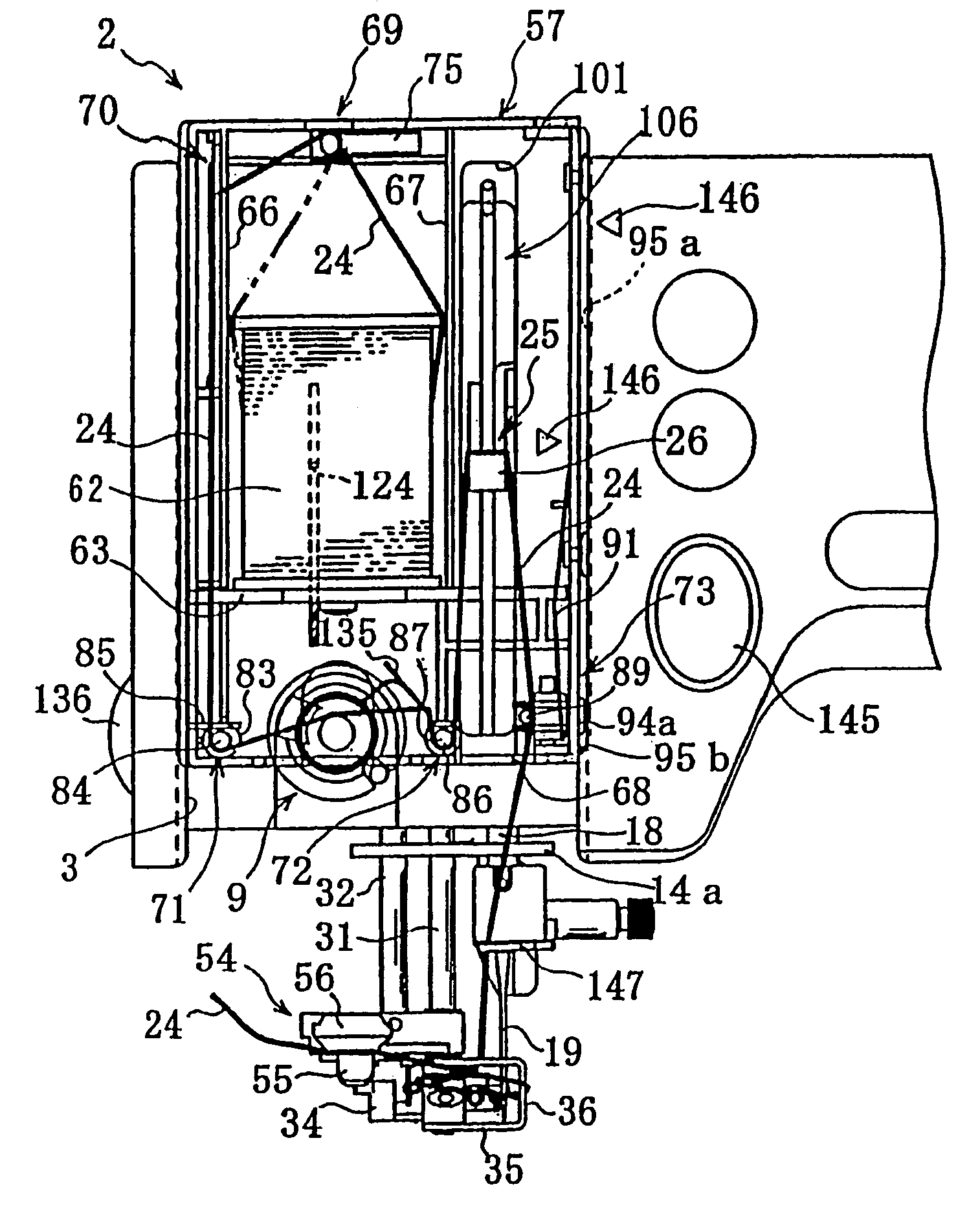
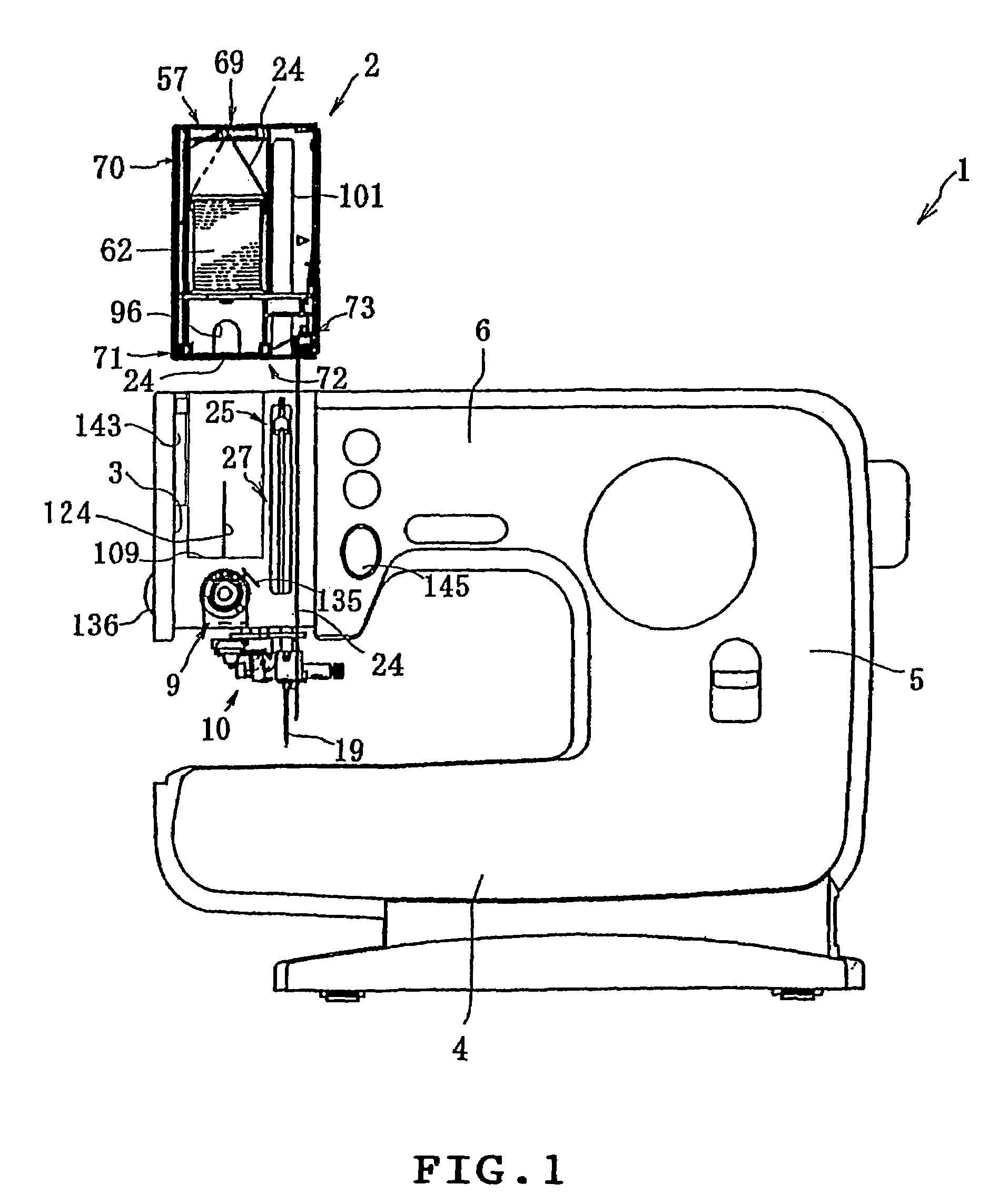
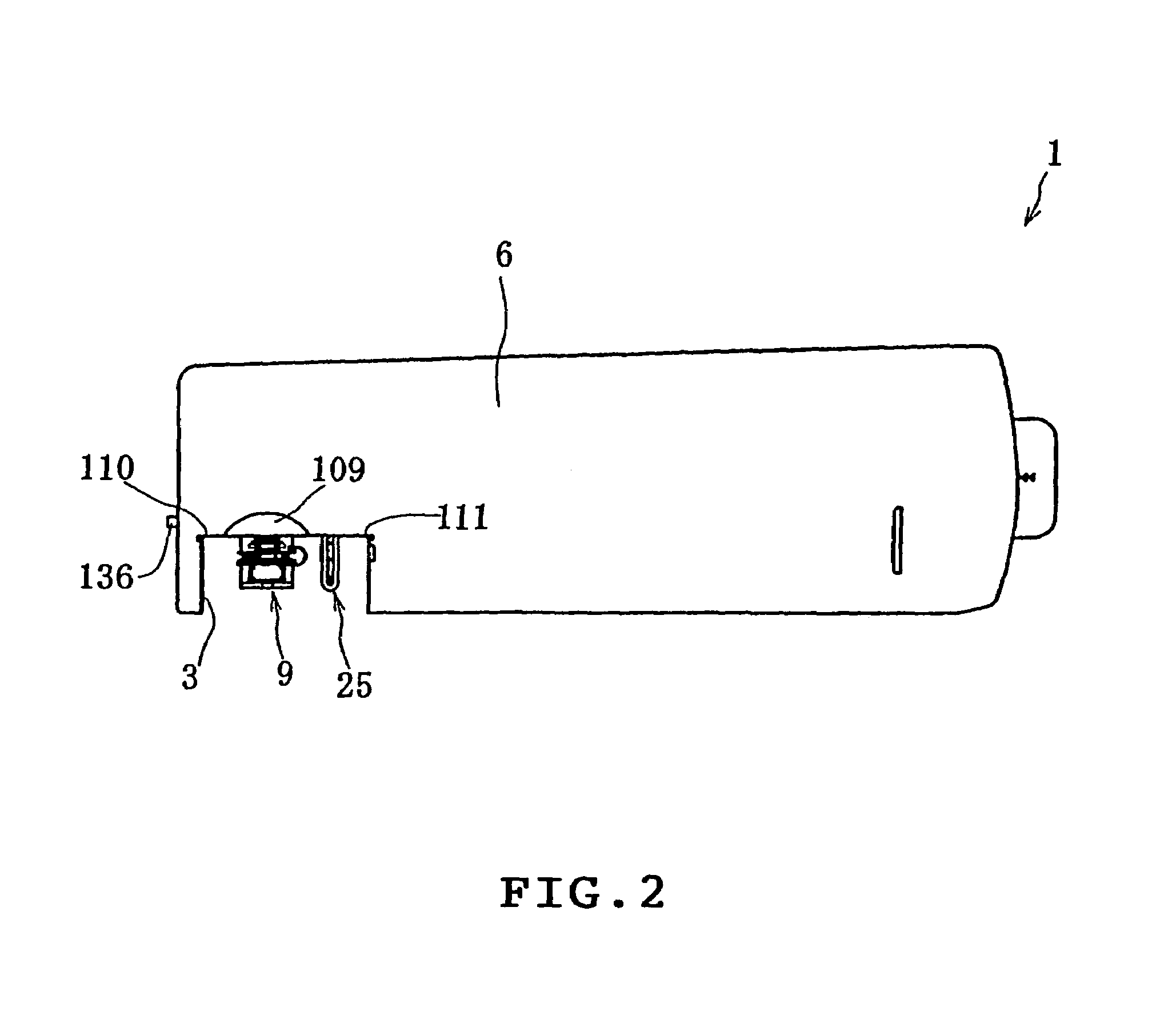
[0089]An embodiment of the invention will be described with reference to the accompanying drawings. This electronic control sewing machine is constructed such that an needle thread cassette housing a thread bobbin can be mounted in a cassette mounting portion of an arm head, and such that an needle thread is engaged with the thread guard of a thread take-up lever and a thread tension regulator and is introduced into the eye of a needle in association with the mounting action to mounting an needle thread cassette 2.

[0090]The description will be made at first on the basic structure of the sewing machine 1 and on a threading mechanism 10, and then on the needle thread cassette 2, a cassette mount 3, a thread take-up lever 8, a transmission mechanism 115 for the threading operation, and an interlocking mechanism 134 for a thread tension regulator 9 sequentially in the recited order. Here, the following description is made by assuming that the front / back and left / right are taken from an ...


PUM


Abstract

A sewing machine includes a thread take-up lever and a thread tension regulator each disposed along a predetermined needle thread passage from a thread bobbin to a needle, an arm having a front face, and a movable controller disposed in the front of the arm so as to be movable at least within a predetermined range. The movable controller does not protrude out of the front face of the arm when moved in the predetermined range. The needle thread is engaged with at least one of the thread take-up lever and the thread tension regulator when the movable controller is moved within the predetermined range while the needle thread has been drawn from the thread bobbin near to the needle substantially along the predetermined needle thread passage.

Description

TECHNICAL FIELD[0001]The present invention relates to a sewing machine, which is provided at its arm with a movable controller made movable at least within a predetermined range, a thread take-up lever and a thread tension regulator and, more particularly, to a sewing machine, which can automatically engage a thread with the thread take-up lever and the thread tension regulator or can automatically pass a thread through a needle.BACKGROUND ART[0002]In an ordinary sewing machine, there are arranged a thread take-up lever mechanism to be driven in an arm by a spindle and a needle bar drive mechanism. A thread take-up lever is partially protruded from a vertical slit in an arm head and is reciprocally driven up and down. The arm is provided with a thread bobbin mount on its upper end side and with a thread tension regulator and a thread tension spring on its front side. A tension dial for the thread tension regulator is provided rear the thread tension regulator. A needle bar protrudes...

Claims


Application Information

Patent Timeline
Patent Type & Authority Patents(United States)
IPC IPC(8): D05B49/00D05B43/00D05B73/00D05B87/02
CPCD05B43/00D05B87/02D05B73/00
Inventor KITAZAWA, HIROSHIHORI, MASAYUKI
Owner BROTHER KOGYO KK
Why Eureka
Try Eureka