Modular fire detection and extinguishing system

a fire detection and extinguishing system technology, applied in fire rescue and other directions, can solve the problems of motor vehicle fire, total loss of vehicle, injuring or killing vehicle occupants, etc., and achieve the effect of suppressing fir

Inactive Publication Date: 2006-01-03
SMITH BRADLEY W +2
View PDF15 Cites 38 Cited by
  • Summary
  • Abstract
  • Description
  • Claims
  • Application Information

AI Technical Summary

Benefits of technology

[0018]The apparatus of the present invention has been developed in response to the present state of the art, and in particular, in response to the problems and needs in the art that have not yet been fully sol...

Problems solved by technology

Vehicle fires may occur in motor vehicles during normal operation or when a vehicle is involved in an accident.
While these kinds of fires may occur infrequently, when they occur, they can transform a minor fuel leak or fender bender into a costly and dramatic vehicle fire requiring significant repairs, resulting in total loss of the vehicle, or most importantly, injuring or killing vehicle occupants and/or by standers.
Often, occupants can escape the fire danger.
However, the property damage can be significant.
In one estimate, in one year, 332,900 light weight vehicle (GVWR<4500 kg) fires were reported in the U.S., resulting in approximately $737 million in property damage.
Often, attempts to extinguish the fire with a manual fire extinguisher are ineffective or endanger the extinguisher operator.
Unfortunately, Automatic fire extinguisher systems (AFES) have deficiencies and problems which limit their wide spread use, particularly with owners of light weight vehicles.
Most importantly, AFES are generally very expensive and complicated when compared with the relatively low risk of a vehicle fire.
Purchasing the components separately increases the overall cost of the system.
These disciplines generally discourage a vehicle owner from installing the AFES.
Expert installation increases the AFES expense.
Furthermore, conventional AFESs are ineffective at extinguishing the fire in certain fire haz...

Method used


Image

  • Modular fire detection and extinguishing system
  • Modular fire detection and extinguishing system
  • Modular fire detection and extinguishing system

Examples


Embodiment Construction

[0035]The present invention can be better understood with reference to the drawings where like parts are designated with like numerals throughout.

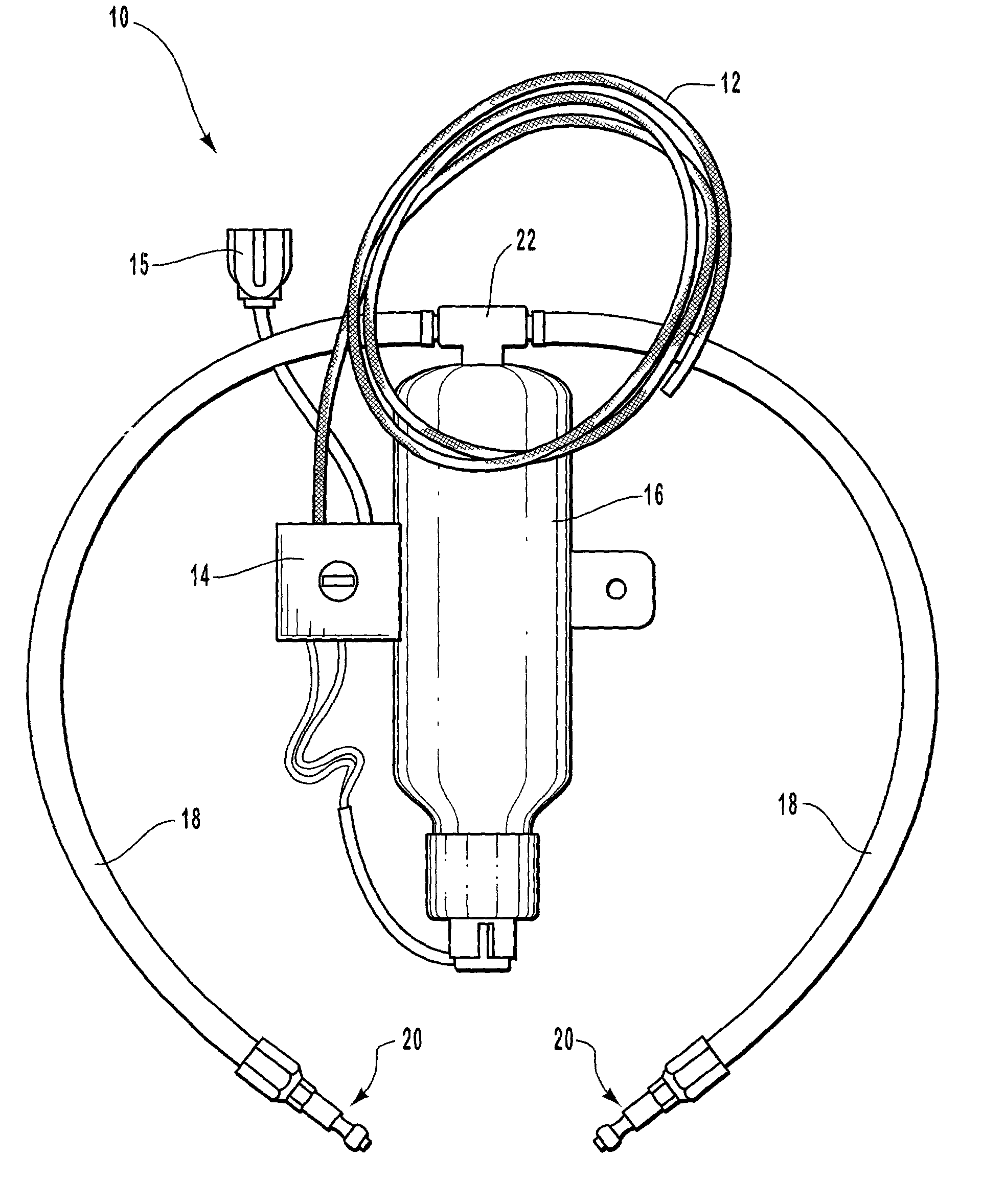
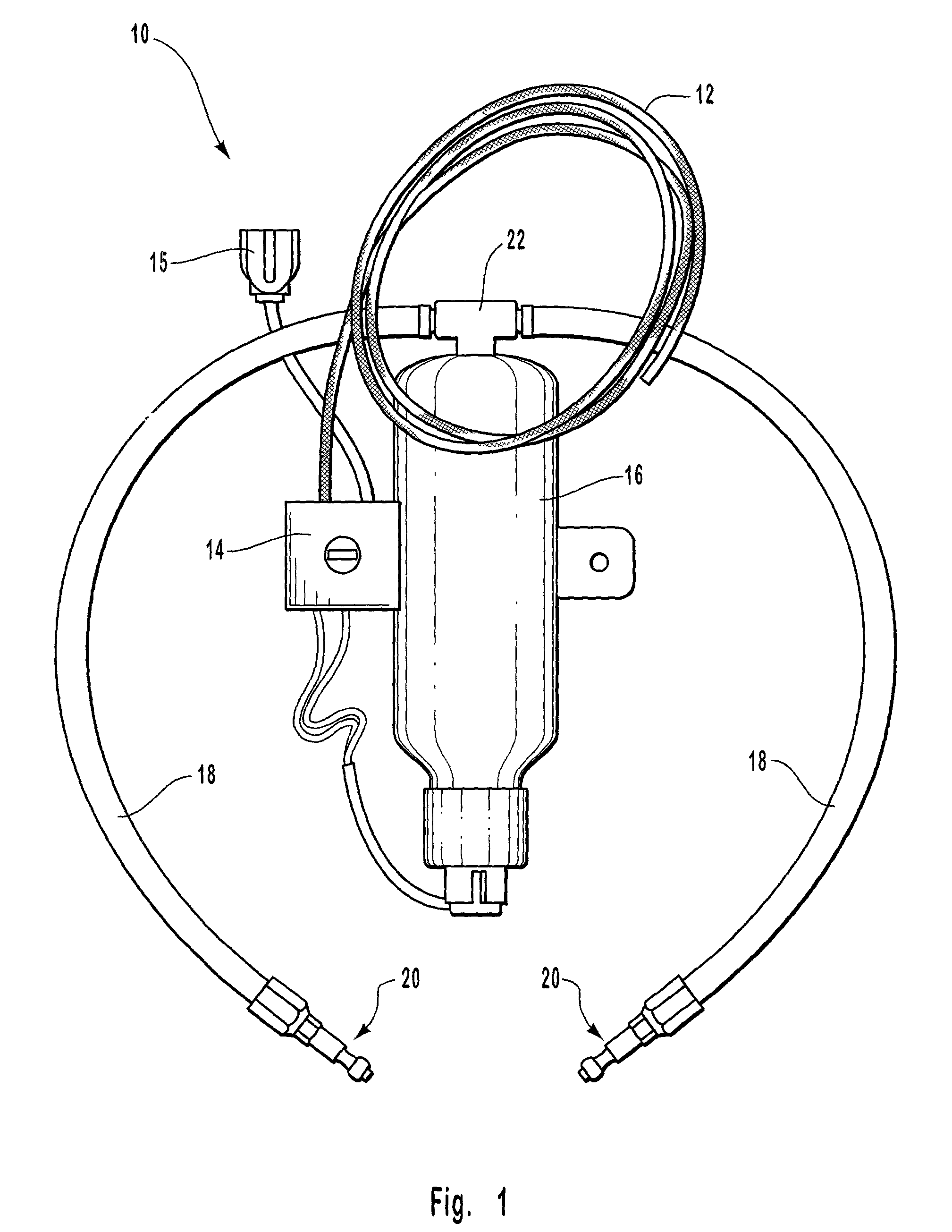
[0036]FIG. 1 is a perspective view illustrating one embodiment of an automatic fire extinguisher system (AFES) 10. The AFES 10 includes a detector 12, a trigger 14, a gas generant fire extinguisher 16, and one or more modular distribution lines 18. Preferably, an AFES 10 is installed in an area which is predisposed to fires in that area, defined as a fire hazard zone. In a preferred embodiment, the fire hazard zone may be an engine compartment of a vehicle. Alternatively, the fire hazard zone may include cooking systems of a kitchen, machinery in a factory, or the like.

[0037]In certain embodiments, the detector 12 is a linear temperature sensitive cable. The cable includes two conductive wires which are covered by insulation. The insulation is designed to melt at a certain temperature. Generally, the melting temperature is such that the de...


PUM


Abstract

A modular fire detection and extinguishing system is disclosed that is inexpensive, compact, and modular to allow easy aftermarket installation in a variety of vehicles. The system may include a detector, a trigger coupled to the detector and a gas generant fire extinguisher, a modular distribution line in fluid communication with the extinguisher and a nozzle. The system allows exhaust gas from the gas generant fire extinguisher to carry dry powdered fire suppressant from the fire extinguisher and through the nozzle to disperse the fire suppressant substantially uniformly throughout a fire hazard zone. The extinguisher is installed such that exhaust gas must aerate substantially all the fire suppressant before exiting the extinguisher.

Description

BACKGROUND OF THE INVENTION[0001]1. The Field of the Invention[0002]The present invention relates to automatic fire detection and extinguishing systems. More specifically, the invention relates to a stand alone compact modular fire detection and extinguishing system.[0003]2. Technical Background[0004]Vehicle fires may occur in motor vehicles during normal operation or when a vehicle is involved in an accident. Generally, these fires begin in the engine compartment. While these kinds of fires may occur infrequently, when they occur, they can transform a minor fuel leak or fender bender into a costly and dramatic vehicle fire requiring significant repairs, resulting in total loss of the vehicle, or most importantly, injuring or killing vehicle occupants and / or by standers.[0005]Often, occupants can escape the fire danger. However, the property damage can be significant. In one estimate, in one year, 332,900 light weight vehicle (GVWR<4500 kg) fires were reported in the U.S., result...

Claims


Application Information

Patent Timeline
IPC IPC(8): A62C3/07A62C3/08A62C35/00A62C37/00A62C37/10A62C13/66A62C13/68A62C37/40
CPCA62C3/07A62C3/08A62C37/40A62C13/68A62C13/66
Inventor SMITH, BRADLEY W.LINDSEY, DAVID W.CLARK, MARCUS T.
Owner SMITH BRADLEY W
Why Eureka
Try Eureka