
Non-parallax optical auto-focusing system and method

an auto-focusing system and non-parallax technology, applied in the field of non-parallax optical auto-focusing system and method, can solve the problems of limiting the response time of the system, prone to errors in the triangulation technique,

Inactive Publication Date: 2006-01-03
SYMBOL TECH INC
View PDF6 Cites 31 Cited by
  • Summary
  • Abstract
  • Description
  • Claims
  • Application Information

AI Technical Summary

Benefits of technology

The system provides instantaneous and real-time auto-focusing without parallax errors, ensuring accurate image focus and distance measurement, adaptable for various devices like cameras and optical code readers.

Problems solved by technology

This triangulation technique is typically prone to errors due to parallax, especially for nearby objects, as is generally the case for optical code readers used to image optical codes.
However, a system employing this principle necessitates additional processing steps to calculate the differences in pixel values and determine the level of contrast in the image of the optical target.
In such a system, the necessity of additional processing steps limits the response time of the system.

Method used


Image

  • Non-parallax optical auto-focusing system and method
  • Non-parallax optical auto-focusing system and method
  • Non-parallax optical auto-focusing system and method

Examples


Embodiment Construction

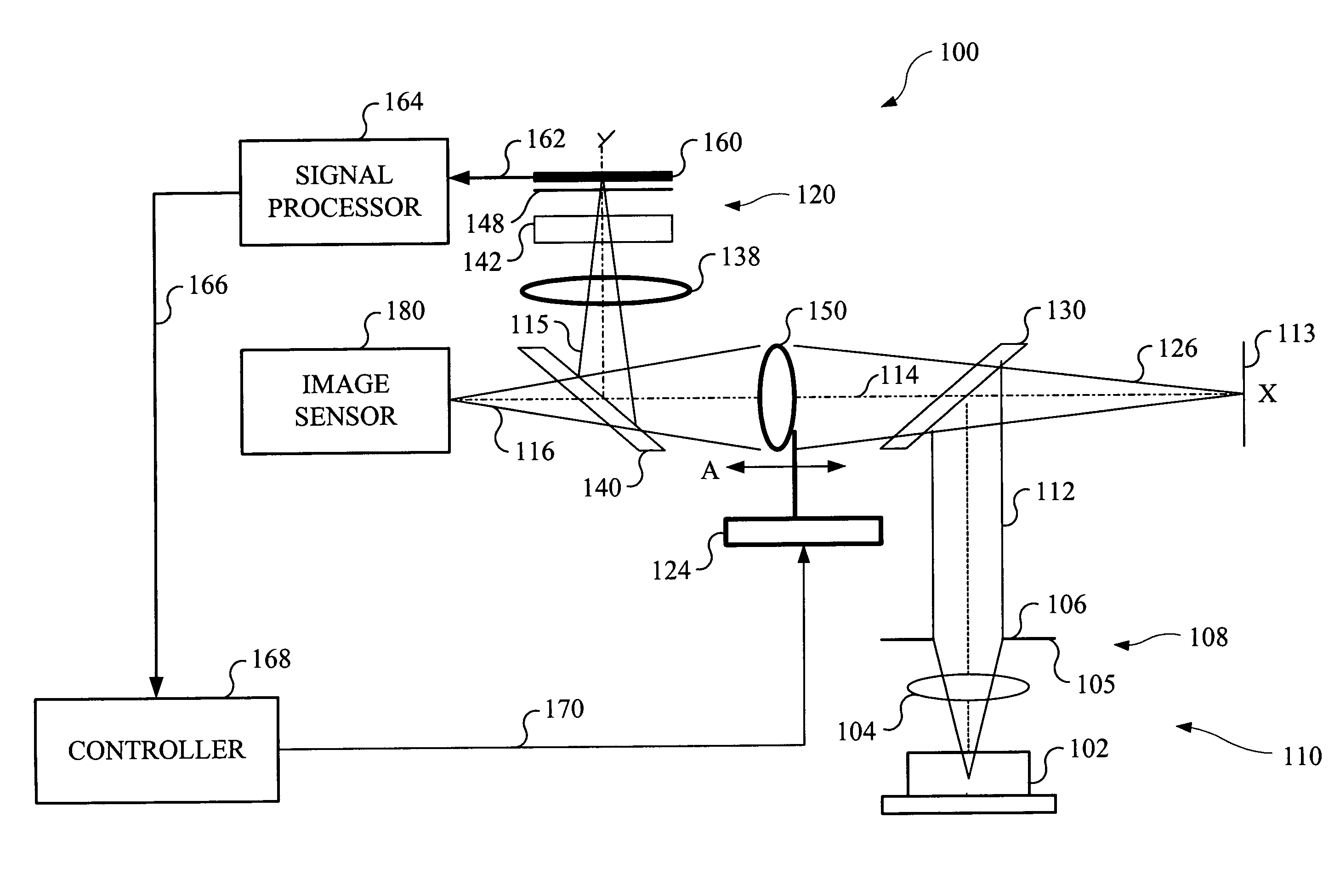
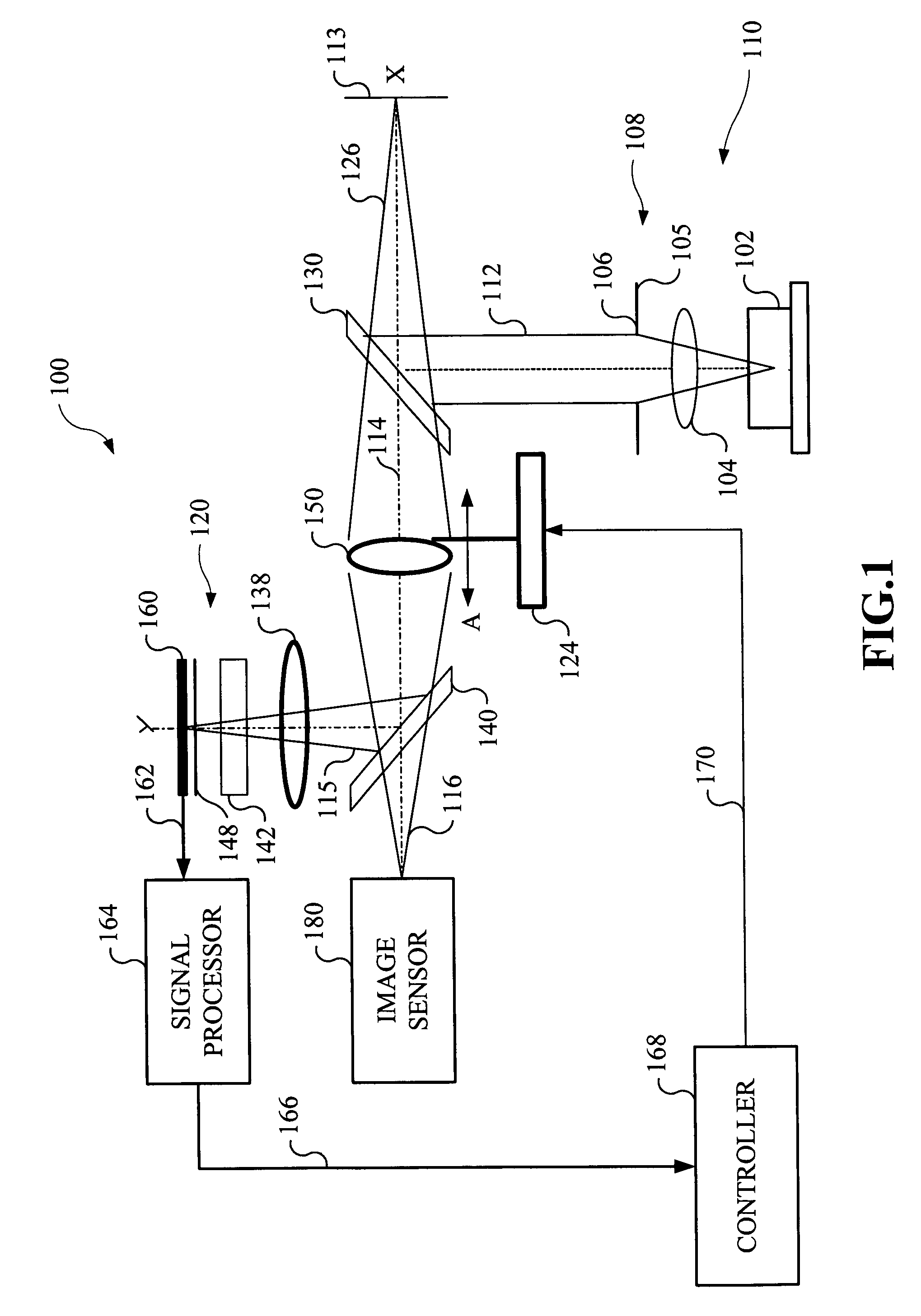
[0028]With reference to FIG. 1, there is illustrated a non-parallax optical auto-focusing system designated generally by reference numeral 100 in accordance with the present invention. FIG. 4 illustrates a flow chart of a method of operation using the system shown in FIG. 1. The non-parallax optical auto-focusing system 100 and method are adaptable and configurable for incorporation in various devices, such as cameras, mobile phones, PDAs, terminals, etc., for providing instantaneous or real-time auto-focusing of an image and without being prone to errors due to parallax.

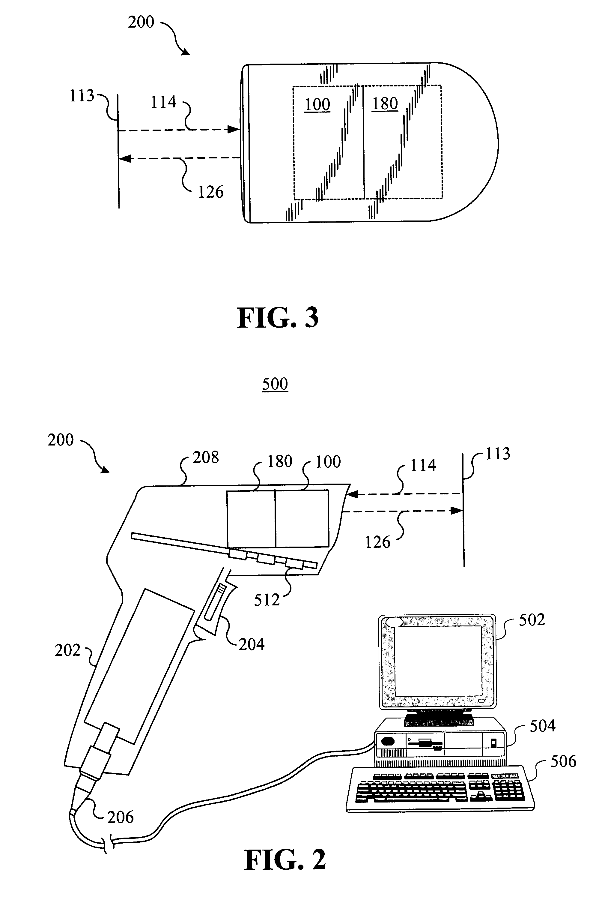
[0029]The system 100 and method are especially suited and described herein for incorporation in optical code readers used for imaging and reading optical codes, such as barcodes. Preferably, the non-parallax optical auto-focusing system 100 is configured and dimensioned to fit within a conventional form factor of an optical code reader 200 (see FIGS. 2 and 3), such as the SE900 and SE1200 form factors developed by S...


PUM


Abstract

A non-parallax optical auto-focusing system focuses an image and determines a distance to an optical target without being prone to errors due to parallax. The system includes a first beam splitter, a second beam splitter, and a lens positioned therebetween on an optical axis. An aiming beam is directed towards an optical target and the redirected reflected beam is received by a quadrant sensor assembly for generating an output signal indicative of a parameter of the redirected reflected aiming beam. A processor receives the output signal and generates a control signal for actuating an actuator to reposition the lens. The system continues to position the lens until the measured parameter is within a predetermined range for optimally focusing the optical target on an image sensor. The distance to the optical target is determined by using a look-up table to correlate the measured parameter to the distance to the optical target.

Description

BACKGROUND OF THE INVENTION[0001]1. Field of the Invention[0002]This invention relates to imaging in optical code reading devices. More particularly, the present invention relates to a non-parallax optical auto-focusing system and method. In particular, the present invention relates to a non-parallax optical auto-focusing system and method for use in mobile and stationary optical code readers.[0003]2. Description of the Related Art[0004]Auto-focusing systems in conventional cameras, optical code readers, etc. generally employ devices to determine the distance between the auto-focus device and the selected target or object before moving one or more lenses for focusing the object. Typically, such devices utilize the triangulation technique for measuring distances.[0005]An image sensor based on the triangulation technique comprises an illumination device, such as an LED or a laser, and a detector, such as CCD. The illumination device projects a light-dot on the object. A proportion of ...

Claims


Application Information

Patent Timeline
Patent Type & Authority Patents(United States)
IPC IPC(8): G06K7/10G02B7/28
CPCG02B7/285G06K7/10811G06K7/10722
Inventor KRICHEVER, MARK
Owner SYMBOL TECH INC
Learn More