Apparatus and methods for removing and installing an upper diaphragm half relative to an upper shell of a turbine

a technology for removing and installing the upper shell and the diaphragm, which is applied in the direction of machines/engines, manufacturing tools, transportation items, etc., can solve the problems of increasing the cost of maintenance and outage time, and the availability of bridge cranes, so as to facilitate inspection and cleaning along the horizontal midline of the upper shell by workers below the shell, and convenient cleaning and inspection

Active Publication Date: 2006-01-03
GENERAL ELECTRIC CO
View PDF18 Cites 7 Cited by
  • Summary
  • Abstract
  • Description
  • Claims
  • Application Information

AI Technical Summary

Benefits of technology

[0004]In a preferred embodiment of the present invention, there is provided a system for removing the upper diaphragm halves from the upper shell of the turbine without inverting the upper shell and replacing refurbished or new diaphragm halves into the upper shell, similarly without inverting the upper shell. To accomplish the foregoing, there is provided a support structure for the upper shell and diaphragm halves. Additionally, individual carts are provided for facilitating the removal of each diaphragm half from the upper shell, refurbishment of the removed diaphragm half and reinstallation of the refurbished or a new diaphragm half into the upper shell. The support structure includes a pair of stands, each having an elongated beam supported by stabilizing and leveling legs and feet. A crane is used to lift the upper shell and associated diaphragm halves from the lower shell and set the horizontal joint faces of the upper shell on the beams. The beams lie at an elevation enabling access to the upper shell and upper diaphragm halves by workmen from below to the horizontal midline of the upper shell and diaphragm halves. That is, the stands support the upper shell and diaphragm halves at a height convenient for cleaning and inspecting the horizontal joint of the upper shell and to remove and install the upper diaphragm halves. Consequently, the pair of stands are designed to support the entire weight of the upper shell and diaphragm halves at an elevation approximately six feet above floor or ground level. Consequently, inspection and cleaning along the horizontal midline of the upper shell by workmen below the shell are facilitated.
[0006]Mounted on the platform is an attachment assembly which includes support block assemblies mounted on the attachment assembly for movement in longitudinal and transverse directions to support the diaphragm half. This horizontal and transverse movement of the support block assemblies enables the support blocks to be adjusted in position depending upon the stage of the diaphragm half being removed. It will be appreciated that the upper diaphragm halves of the turbine stages have different horizontal midline configurations including obstructions at their midlines. The support block assemblies are therefore adjustable to enable each platform to engage and accommodate the different configurations and obstructions of each diaphragm half whereby the support block assemblies are common to the different configurations of the diaphragm halves at their midlines. The carts preferably also have outrigger assemblies such that the floor or ground supporting footprint of the carts can be enlarged to afford greater stability to the carts when the diaphragm halves are supported by the carts. In a preferred embodiment, the outrigger assemblies include telescoping legs mounting the wheels of the cart between extended and contracted positions. Also, the lifting system for each cart includes hydraulics and the scissors arrangement encased in an enclosure between the base of the cart and the platform. The enclosure may, for example, take the form of a bellows. The enclosure serves to protect the lift mechanism and hydraulic system during cleaning and servicing of the upper shell and diaphragm halves.
[0007]To employ the system thereof, the upper and lower shells are unbolted from one another, and the upper shell and upper diaphragm halves are lifted by a crane for disposition on the stands. The orientation of the upper shell remains as it was in the turbine with the upper diaphragm half midlines facing downwardly. It will be appreciated that the bolt and key arrangements maintain the diaphragm halves in the upper shell and prevent them from falling out of the upper shell. Once the upper shell is placed on the stands, a cart with its platform in a retracted position is disposed below the upper shell and in vertical registration with a diaphragm half to be removed. The cylinder is actuated to engage the platform and the upper diaphragm half along its midline and bolts are inserted into existing bolt holes of the upper diaphragm half to secure the upper diaphragm half to the platform. By subsequently incrementally elevating the platform, the weight of the upper diaphragm half secured to the platform is transferred to the cart. The bolt and key arrangements are then removed to release the upper diaphragm half from the upper shell. The cylinder is then actuated to retract or lower the platform and the diaphragm half secured thereto. When the diaphragm half clears the lower margin of the upper shell, the cart is moved from below the upper shell and from between the stands to another location for servicing. A similar cart is used for removing and refurbishing each of the diaphragm halves whereby all of the diaphragm halves of the upper shell can be removed for servicing without inversion of the upper shell.
[0009]It will be appreciated from the foregoing that while a crane is needed to lift the upper shell and diaphragms from the lower shell, a second crane is not necessary to invert the upper shell. Additionally, with the foregoing arrangement, the midline joints of the upper shell can also be readily refurbished by workmen from positions below the upper shell.

Problems solved by technology

At many sites for turbines, bridge cranes are not available and two boom-type cranes are required for this lifting process.
It will be appreciated that the requirement for two cranes substantially increases the cost of performing the maintenance as well as the outage time.

Method used


Image

  • Apparatus and methods for removing and installing an upper diaphragm half relative to an upper shell of a turbine
  • Apparatus and methods for removing and installing an upper diaphragm half relative to an upper shell of a turbine
  • Apparatus and methods for removing and installing an upper diaphragm half relative to an upper shell of a turbine

Examples


Embodiment Construction

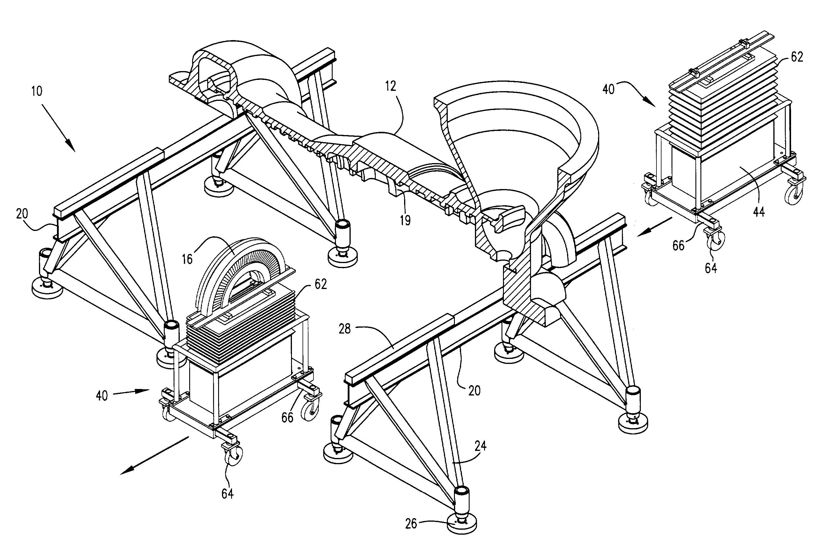
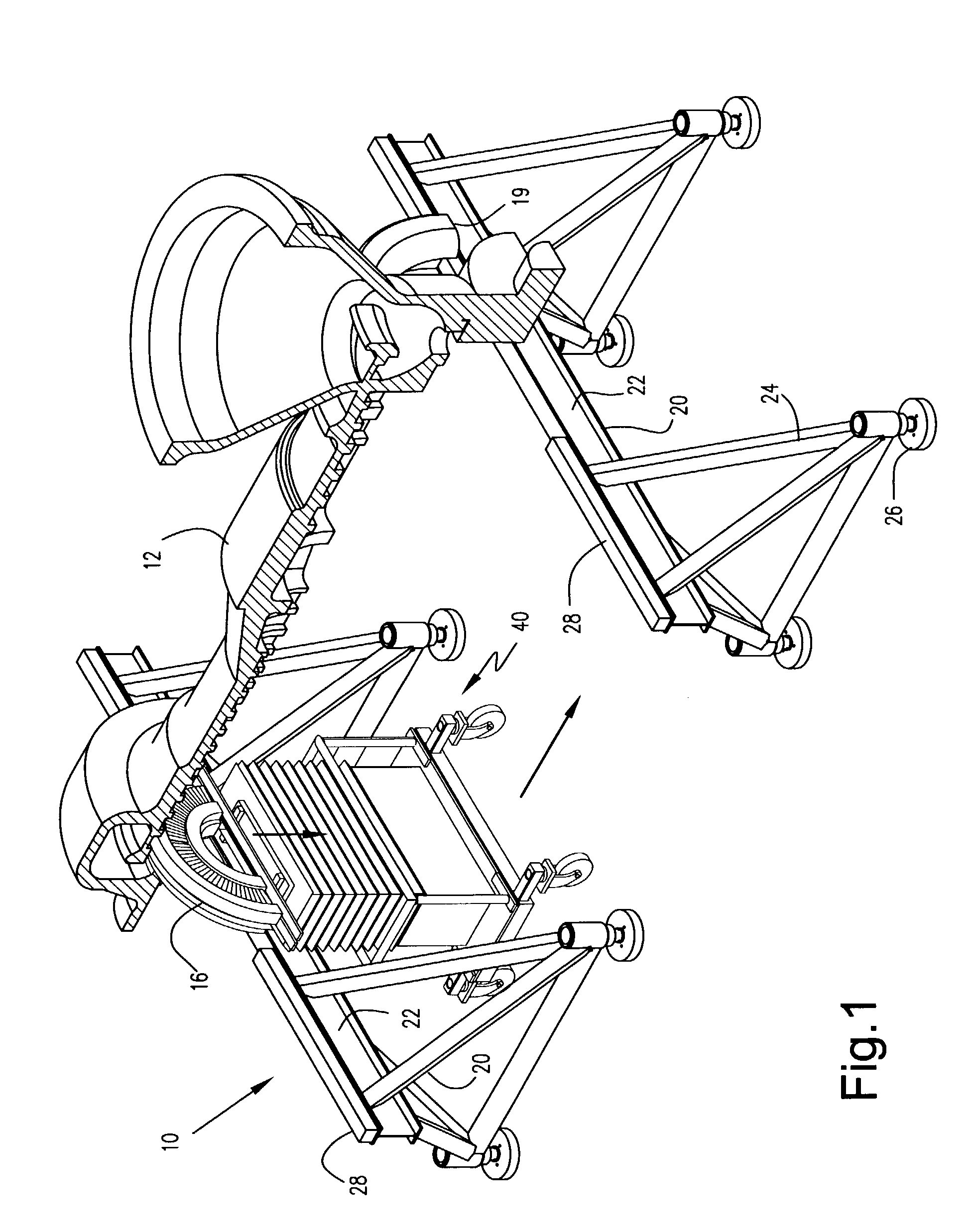
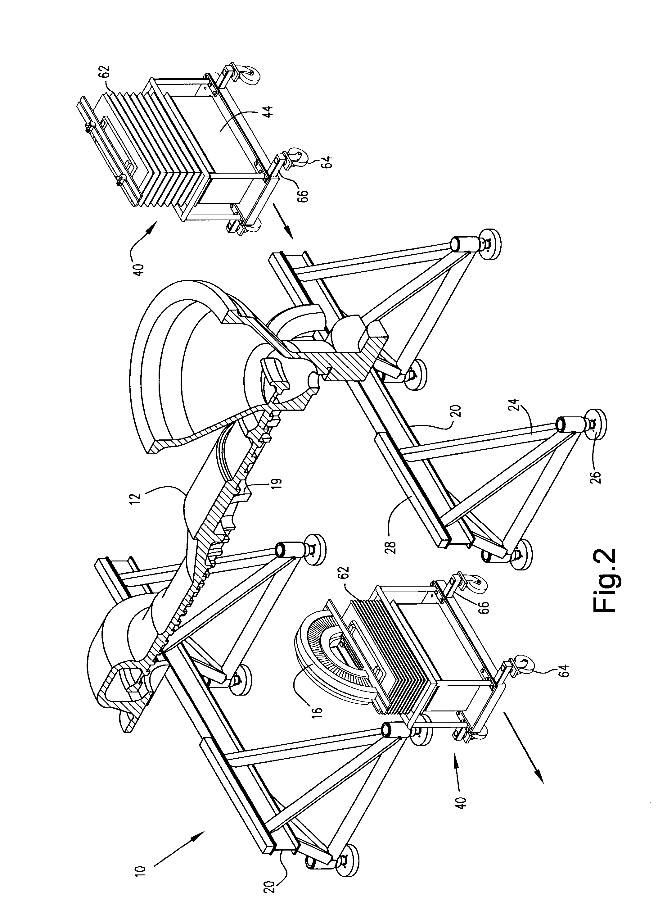
[0021]Referring now to the drawings, particularly to FIG. 1, there is illustrated a system for removing upper shell diaphragm halves to and from the upper shell of a turbine and reinstalling refurbished or new upper shell diaphragm halves into the upper shell, the system being generally designated 10. Illustrated in FIG. 1, in partial cross-section, is an upper shell 12 of a turbine, for example, a steam turbine. As will be appreciated, upper shell 12 has a horizontal midline joint 19 in a plane along the axis of the turbine. In FIG. 1, the midline joint faces downwardly, similarly as its orientation when secured to the lower shell, not shown, of the turbine. Also in FIG. 1, there is illustrated an upper diaphragm half 16 forming in part one of the multiple stages of the turbine. The lower shell, not shown, of the turbine likewise includes a horizontal midline joint, and the upper and lower shells are bolted one to the other along the corresponding horizontal midline joints. The low...


PUM

PropertyMeasurementUnit
weightaaaaaaaaaa
elevationaaaaaaaaaa
outage timeaaaaaaaaaa

Abstract

A pair of stands are spaced one from the other to support opposite ends of an upper shell and diaphragm halves of a turbine at locations along the upper shell axially beyond the diaphragm halves. Carts mounted on wheels each have a hydraulically actuated lift and a platform mounting support assemblies engagable with an upper diaphragm half at the midline. By engaging a diaphragm half from below the upper shell, securing the support assemblies to the upper diaphragm half and releasing the upper diaphragm half from the upper shell by removing bolts and keys to transfer the weight of the diaphragm half to the cart, the diaphragm half may be lowered from the upper shell and moved away. The diaphragm halves may then be refurbished and the process reversed to reinstall the diaphragm halves into the upper shell. During the process, the upper shell remains in its normal orientation, similarly as in the turbine.

Description

BACKGROUND OF THE INVENTION[0001]The present invention relates to a system for removing diaphragm halves from an upper shell of a turbine, moving the removed diaphragm halves to a location for refurbishing, and reinstalling the refurbished diaphragm halves into the upper shell.[0002]Turbines, for example steam turbines, periodically require maintenance and generally include upper and lower shells which must be separated from one another along a horizontal midline for that purpose. As will be appreciated, each stage of a turbine includes an annular diaphragm split in half to provide upper and lower diaphragm halves in the upper and lower shells, respectively. The diaphragm halves in the upper shell are typically secured in the upper shell by bolt and key keeper arrangements located adjacent the midline horizontal joint along opposite sides of the turbine. Consequently, when maintenance is required, the upper turbine shell is unbolted from the lower shell and the upper shell, includin...

Claims


Application Information

Patent Timeline
Patent Type & Authority Patents(United States)
IPC IPC(8): B66F11/00B23P19/04F01D25/28
CPCF01D25/285Y10T29/49318F05D2230/70F05D2230/80
Inventor TOMKO, ANDREW JOHNNOLAN, JOHN FRANCISANDERSON, III, KARL RUDOLPH
Owner GENERAL ELECTRIC CO
Why Eureka
Try Eureka