Connector

Inactive Publication Date: 2006-01-03
FUJITSU COMPONENENT LTD
View PDF17 Cites 23 Cited by
  • Summary
  • Abstract
  • Description
  • Claims
  • Application Information

AI Technical Summary

Benefits of technology

[0019]It is therefore an object of the present invention to provide a connector that has multiple pairs of sig

Problems solved by technology

For this type of data transmission, unbalanced transmission methods have been widely employed conventionally, because they are advantageous in terms of costs.
By the unbalanced transmission methods, however, it is difficult to avoid adverse influence of noise.
With the above conventional connector device, however, there is a problem that desired balanced transmission cannot be carried out, because the mating lower ends 4c-2 and 4d-2 extend in the opposite directions and cannot establish preferable

Method used


Image

  • Connector
  • Connector
  • Connector

Examples


first embodiment

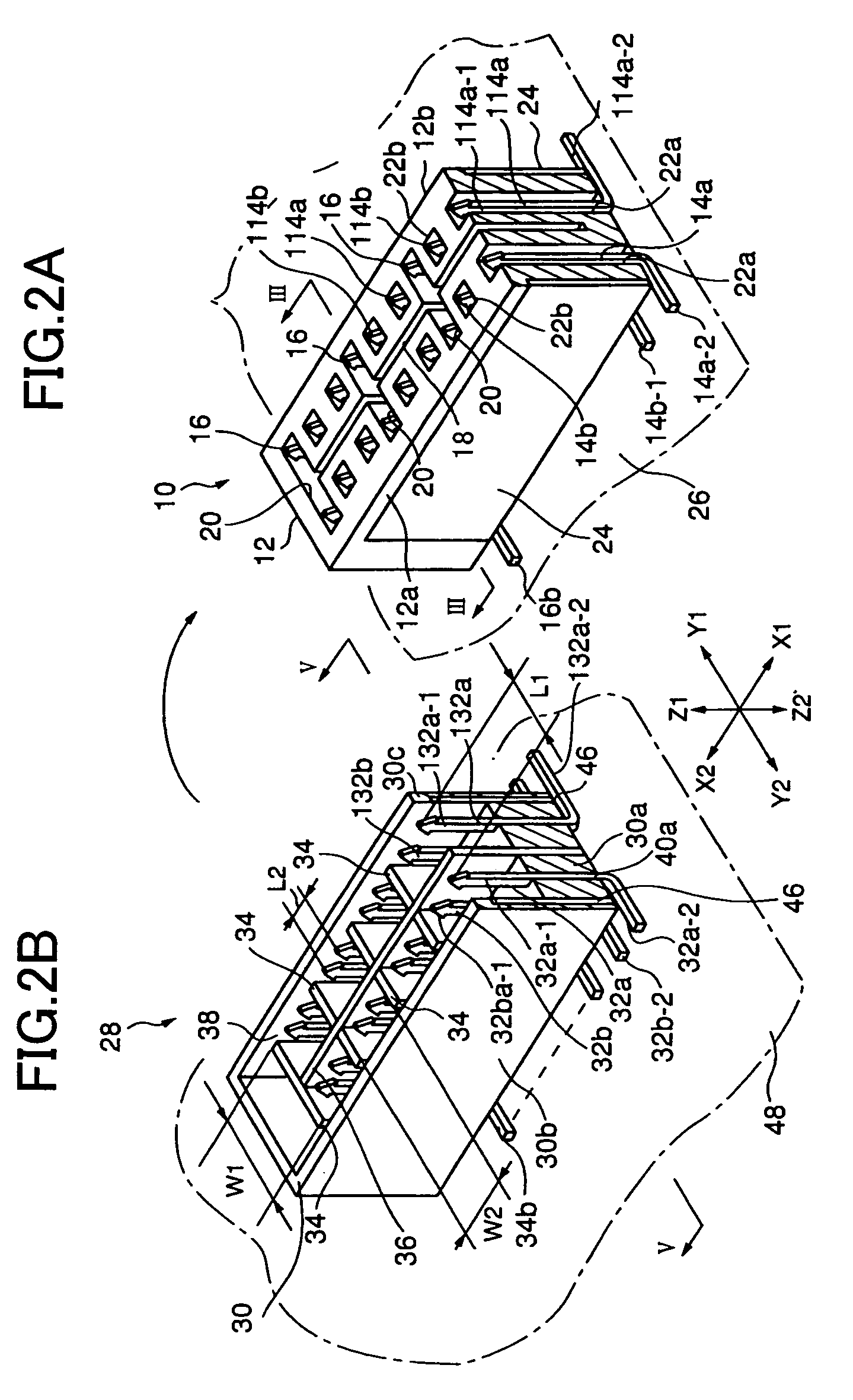
[0078]Referring first to FIGS. 2A through 6B, a connector in accordance with a first embodiment of the present invention will be described.

[0079]The connector in accordance with this embodiment is made up of a jack connector and a plug connector that can be connected to the jack connector. The jack connector and the plug connector are set as a pair on substrates, so as to connect multiple substrates to one another. The wiring substrates onto which the connectors of the present invention are mounted are one embodiment of an electronic device of the present invention.

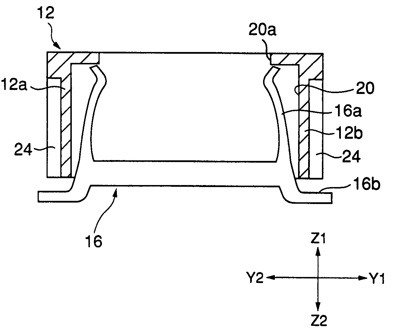
[0080]A jack connector 10 has an array of pairs of signal contacts 14a and 14b, another array of pairs of signal contacts 114a and 114b, and ground contacts 16 in a housing 12 that is made of an insulating material and is formed longitudinally in the direction of X1-X2 of FIG. 2A.

[0081]The housing 12 has a slit 18 that is formed longitudinally in the direction of X1-X2, and short slits 20 that cross the slit 18 at right a...

second embodiment

[0103]Referring now to FIGS. 7A through 9, a connector in accordance with a second embodiment of the present invention will be described.

[0104]The connector in accordance with this embodiment includes a jack connector and a plug connector. Like the jack connector 10 and the plug connector 28 in the first embodiment, the jack connector and the plug connector are mounted on substrates, so as to connect multiple substrates. Although the connector in accordance with the first embodiment has a face-to-face connection mechanism in which the substrates are stacked on one another, the connector in accordance with the second embodiment described below has a horizontal connection mechanism in which the ends of substrates are connected to one another.

[0105]As shown in FIGS. 7A and 7B, in a jack connector 50 and a plug connector 52, a pair of signal contacts 54a and 54b (hereinafter referred to simply as the “contacts”) and a ground contact 58 (hereinafter referred to simply as the “contact”) f...

third embodiment

[0124]A connector in accordance with a third embodiment of the present invention will be next described.

[0125]FIGS. 10A through 10D illustrate a plug connector 210 in accordance with the third embodiment. More specifically, FIG. 10A is a perspective view of the connector 210, FIG. 10B is a partially cutaway perspective view of the connector 210, FIG. 10C is a sectional view of the connector 210 taken along the line XC of FIG. 10B, and FIG. 10D is a sectional view of the connector 210 taken along the line XD of FIG. 10B.

[0126]The connector 210 includes a housing 211 having a concavity 212. The housing 211 is made of an insulating material such as polyester or LCP (Liquid Crystal Polymer) resin. A contact supporting member 213 extending in the longitudinal direction of the connector 210 is provided in the concavity 212. The contact supporting member 213 may be integrally formed with the housing 211, and is shaped like a flat panel. The contact supporting member 213 has two planes faci...


PUM


Abstract

A connector includes multiple pairs of signal contacts arranged in a housing, and facilitates the wiring design and the wiring operation for substrates. The two signal contacts in each of the multiple pairs are arranged at a distance in the longitudinal direction of the housing. With this arrangement, excellent coupling can be established between the two signal contacts, and signals can be balanced-transmitted without causing a phase difference. Also, the lengths of each pair of wires of a wiring substrate to be connected to the multiple pairs of signal contacts can be easily made uniform. Accordingly, there is no need to prepare excessive wiring areas, and the substrate wiring design and the wiring operation can be simplified.

Description

[0001]This application is a continuing application, filed under 35 U.S.C. §111(a), of International Application PCT / JP02 / 00677, filed Jan. 30, 2002.BACKGROUND OF THE INVENTION[0002]1. Field of the Invention[0003]The present invention relates to connectors that are used in computers, servers, and routers, and more particularly, to a connector that has multiple pairs of signal contacts and is suitable especially for balanced transmission.[0004]2. Description of the Related Art[0005]In recent years, there has been an increasing demand for a large amount of data transmission, as computers and computer networks have been rapidly developed. Especially, video data transmission needs to be carried out at a speed of 1 Gbit / s or higher.[0006]For this type of data transmission, unbalanced transmission methods have been widely employed conventionally, because they are advantageous in terms of costs. By the unbalanced transmission methods, however, it is difficult to avoid adverse influence of n...

Claims


Application Information

Patent Timeline
IPC IPC(8): H01R13/648H01R12/71H01R13/6585H01R13/6594
CPCH01R23/688H01R12/716H01R13/6594Y10S439/941H01R13/6585Y10S439/931H01R12/00
Inventor AKAMA, JUNICHIHAMAZAKI, MASAHIROKUMAMOTO, TADASHISHIMIZU, MANABUMIYAZAWA, HIDEOKUROTORI, FUMIOUENO, MORIYUKI
Owner FUJITSU COMPONENENT LTD
Why Eureka
Try Eureka