Method and apparatus to regulate loads

a technology of torque regulator and load, applied in the field of controllers, can solve the problems of increasing the slip rate, increasing the rotor generated field and thus the force or torque between the rotor and the stator field, and the regulation scheme adopted is not very accurate, so as to achieve a simple and accurate torque regulator and easy to control system.

Inactive Publication Date: 2006-01-03
ROCKWELL AUTOMATION TECH
View PDF16 Cites 67 Cited by
  • Summary
  • Abstract
  • Description
  • Claims
  • Application Information

AI Technical Summary

Benefits of technology

[0012]It has been recognized that easily obtainable control system signals can be obtained and used to generate an essentially real time instantaneous torque estimate value that can in turn be used to drive a torque trim regulator thereby generating a torque command value that can in turn be used to trim a reference voltage value thus driving the torque applied to an induction machine toward a reference and desired torque value. The torque estimate can be derived by combining feedback current values with several different sets of obtainable system signals. Thus, a simple and accurate torque regulator can be configured.

Problems solved by technology

An increase in slip increases the rate at which flux lines are cut by the rotor, increasing the rotor generated field and thus the force or torque between the rotor and stator fields.
While torque regulation has been contemplated in the past, unfortunately the regulation schemes adopted have not been very accurate.
Unfortunately, the term proportional to operating speed is a relatively inaccurate estimate of motor flux reduction and therefore torque regulation via one of these schemes is not very accurate.
In addition, while system torque can change rapidly, operating frequency changes relatively slowly and therefore, in some cases, stability problems have been known to occur when operating frequency is used as an estimator of flux reduction.
While such inaccurate torque regulators may work in some applications, such limited regulating capabilities are not acceptable for other applications.

Method used


Image

  • Method and apparatus to regulate loads
  • Method and apparatus to regulate loads
  • Method and apparatus to regulate loads

Examples


first embodiment implementation

[0046]B. First Embodiment Implementation

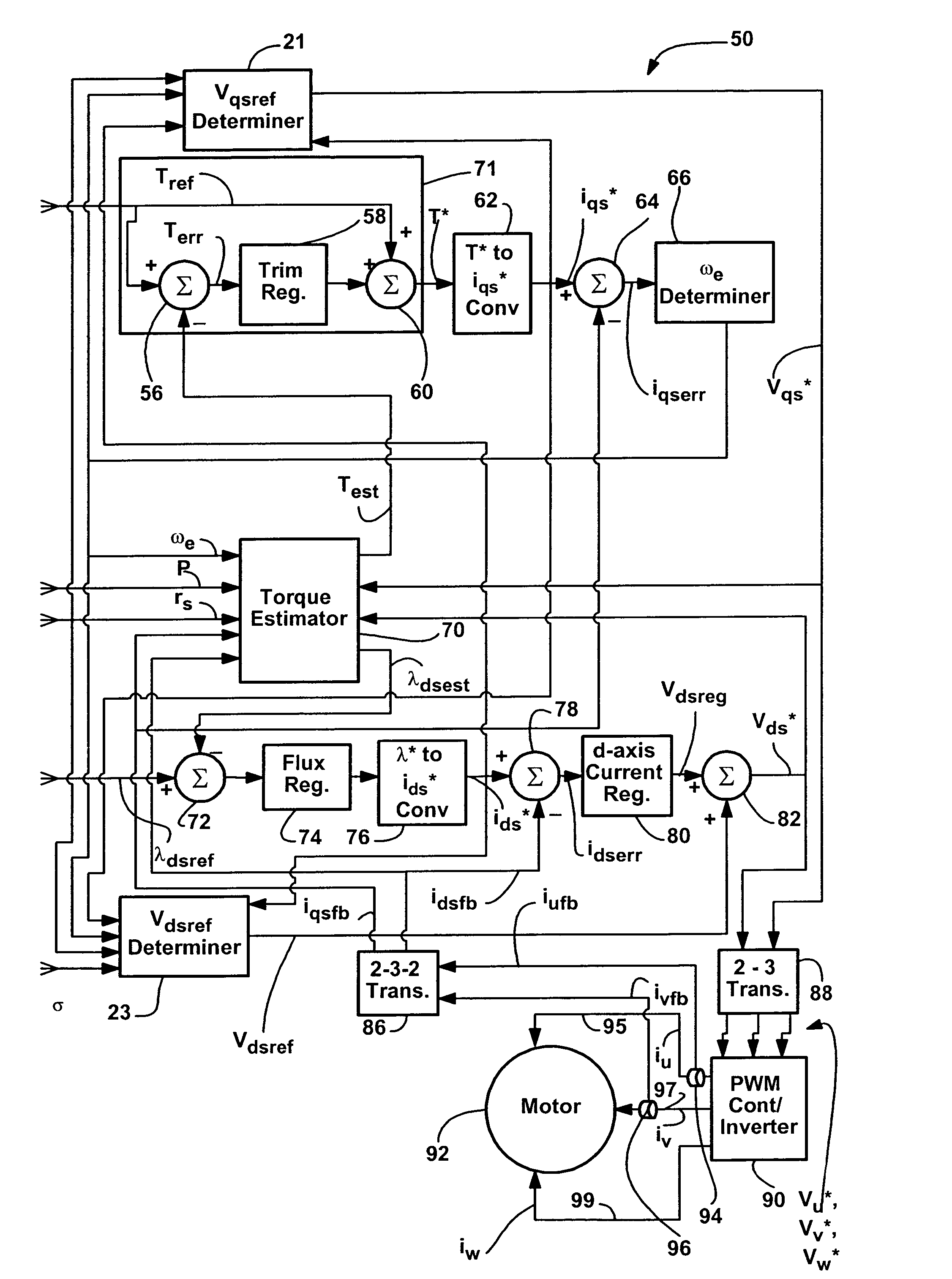
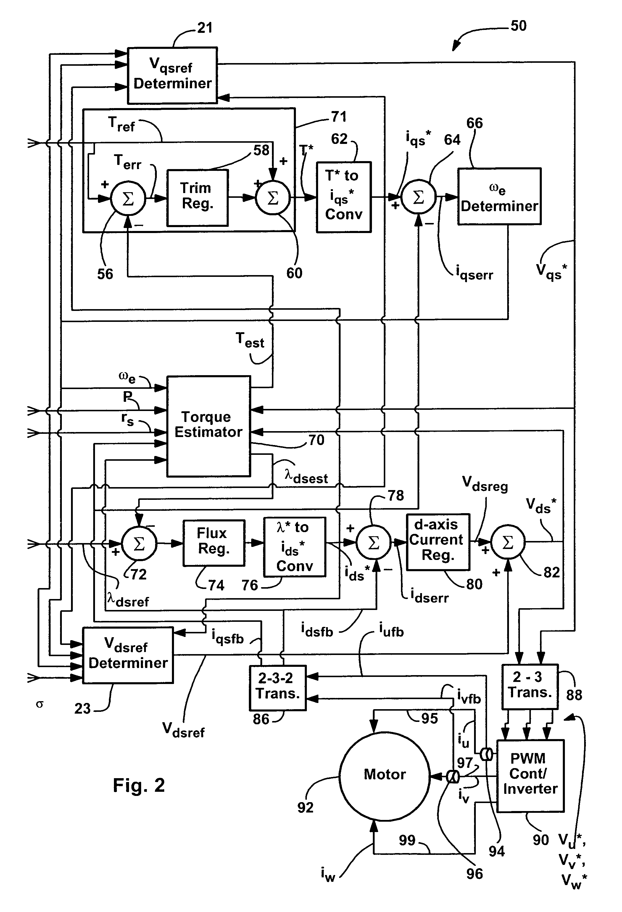
[0047]Referring now to the drawings wherein like symbols and numerals are used to refer to similar elements throughout the several views and, more specifically, referring to FIG. 2, the present invention will be described in the context of an exemplary motor control system 50 that, in general, receives both a torque reference signal Tref and a d-axis flux reference signal λdsref and uses those two signals to generate AC voltages on three separate supply lines 95, 97, 99 linked to motor 92. System 50 includes various feedback loops that enable essentially instantaneous and real time control of torque applied to motor 92 so that the applied torque can be made essentially equal to the reference torque value Tref. In FIG. 2, two current sensors 94 and 96 (e.g., Hall effect sensors) are coupled to two of the three supply lines (e.g., 95 and 97) that are linked to motor 92 to sense currents passing therethrough and generate feedback current signals ...


PUM


Abstract

A method and apparatus for use with a controller for controlling a machine wherein a torque reference value is provided, the method for identifying an error representative of the difference between the torque reference value and the torque applied to the machine and using the error value to modify machine operation, the method comprising the steps of obtaining feedback current values corresponding to the currents provided to the machine, mathematically combining the feedback current values to generate an error value, mathematically combining the error value and the torque reference value to generate a torque command value and using the torque command value to control the machine.

Description

CROSS-REFERENCE TO RELATED APPLICATIONS[0001]Not applicable.STATEMENT REGARDING FEDERALLY SPONSORED RESEARCH OR DEVELOPMENT[0002]Not applicable.BACKGROUND OF THE INVENTION[0003]The present invention relates to controllers providing adjustable frequency currents to loads and more specifically, to a method and apparatus to regulate torque provided to loads.Induction Motors[0004]Induction motors have broad application in industry, particularly when large horsepower is needed. A three phase induction motor receives three phases of electrical voltage to produce a rotating magnetic stator field. A rotor contained within the stator field experiences an induced current (hence the term induction) which generates a rotor field. The interaction of the rotor field and the stator field causes rotation of the rotor.[0005]A common rotor design is a “squirrel cage winding” in which axial conductive bars are connected at either end by shorting rings to form a generally cylindrical structure. The flu...

Claims


Application Information

Patent Timeline
Patent Type & Authority Patents(United States)
IPC IPC(8): H02P7/00H02P21/00H02P21/08
CPCH02P21/0042H02P21/085H02P21/10H02P2207/01H02P2205/05H02P21/09H02P21/26
Inventor SEIBEL, BRIAN J.KERKMAN, RUSSEL J.
Owner ROCKWELL AUTOMATION TECH
Why Eureka
Try Eureka