Accurate and efficient sensing circuit and method for bi-directional signals

a sensing circuit and bi-directional signal technology, applied in the field of current sensing circuits, can solve the problems of reducing the dynamic range of output generated by conventional bi-directional current sensing circuits employing current mirror circuitry, erroneous results can be generated, and the element elements of current mirrors are difficult to match, etc., to achieve accurate and efficient effects

Inactive Publication Date: 2006-01-03
KYOCERA CORP
View PDF19 Cites 6 Cited by
  • Summary
  • Abstract
  • Description
  • Claims
  • Application Information

AI Technical Summary

Benefits of technology

[0010]According to various embodiments, one or more of benefits may be realized by the sensing circuit including, for example, improved dynamic range, improved current sensing accuracy, reduced device complexity, reduced manufacturing costs, improved battery capacity gauging and accurate battery charge monitoring for battery-operated devices, among others.

Problems solved by technology

Due to a number of variations, such as variations in process and temperature, for example, the elements of the current mirror are very difficult to match.
As a consequence, erroneous results can be generated by such bi-directional current sensing circuits.
Furthermore, the output generated by conventional bi-directional current sensing circuits employing current mirror circuitry has significantly reduced dynamic range since a reference voltage between ground and the supply voltage (“VCC”) is used to differentiate between charge current and discharge current.
According to this example, the resolution of the output voltage is reduced by factor of two, significantly diminishing the dynamic range of the sensing circuit output.
However, such complex circuits result in significantly increased components and silicon area consumption, thereby increasing expense and reducing yield, which are undesirable.

Method used


Image

  • Accurate and efficient sensing circuit and method for bi-directional signals
  • Accurate and efficient sensing circuit and method for bi-directional signals
  • Accurate and efficient sensing circuit and method for bi-directional signals

Examples


Embodiment Construction

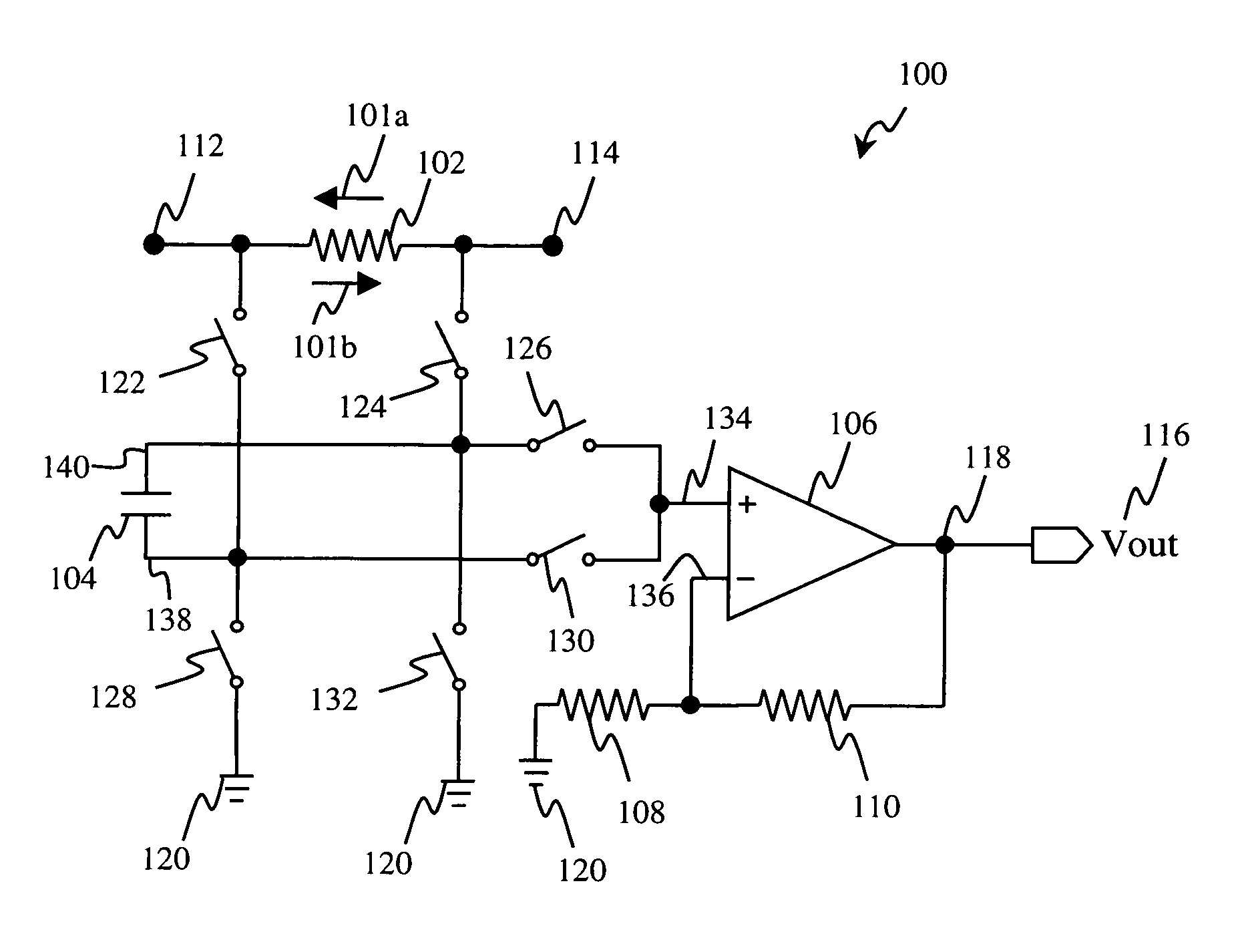
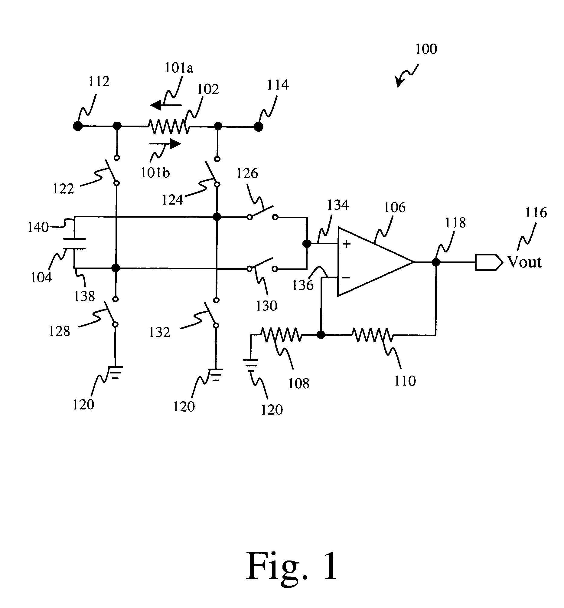
[0014]Referring first to FIG. 1, there is shown exemplary current sensing circuit 100 in accordance with one embodiment of the present invention. As discussed below, sensing circuit 100 is capable of accurately sensing bi-directional signals that flow through resistor 102 including current 101a from node 114 to node 112 and current 101b from node 112 to node 114 in an accurate and efficient manner.

[0015]By way of illustration, sensing circuit 100 is suitable for use in detecting charge current and discharge current in a portable device, such as a mobile communication device or a wireless handset device. A typical mobile communication device includes, among other things, a transceiver for transmitting and receiving an RF signal, and a mobile power source, such as a battery or fuel cell, coupled to the transceiver for supplying power to the transceiver. As such, sensing circuit 100 may be integrated into a mobile communication device to provide accurate battery capacity gauging and ac...


PUM


Abstract

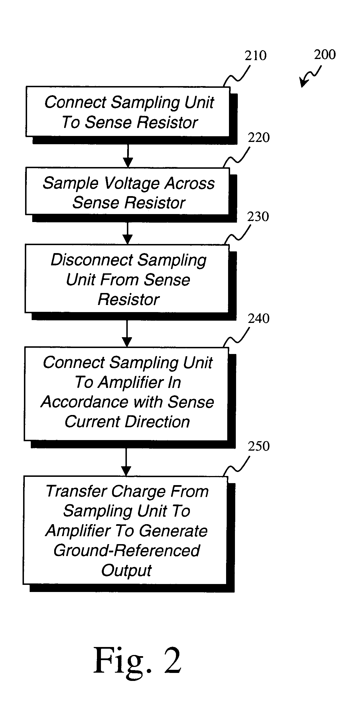
An exemplary circuit for sensing bi-directional current through a resistive element comprises a sampling unit, a charge transfer unit, and an amplifier. The sampling unit is switchably coupled to the resistive element and samples and stores a voltage corresponding to a current flowing through the resistive element. The charge transfer unit switchably connects the sampling unit to the amplifier such that the charge transfer unit and the amplifier convert the sampled voltage to a ground-referenced output voltage corresponding to the magnitude of the current and in accordance with the direction of the current through resistive element.

Description

BACKGROUND OF THE INVENTION[0001]1. Field of the Invention[0002]The present invention relates to the field of semiconductor devices. More specifically, the invention relates to current sensing circuits.[0003]2. Related Art[0004]Sensing circuits have been in wide use for detecting the current drawn through an electrical path or circuit loop in a variety of applications. For example, often it is desirable to ascertain the charge capacity of a battery for an electronic device in order to determine and / or display how long the device can be operated by a user. A known technique for ascertaining the charge capacity of battery involves measuring the discharge current drawn from the battery during operation and correlating the magnitude of the discharge current to the charge capacity level of the battery, as is known in the art.[0005]In general, sensing circuits determine the discharge current by measuring the voltage across a resistor (also referred to as a “sense resistor”), where the sen...

Claims


Application Information

Patent Timeline
Patent Type & Authority Patents(United States)
IPC IPC(8): G01R27/02H04B1/04G01R1/20G01R19/00
CPCG01R19/0092G01R1/203
Inventor TAYLOR, JOHN P.
Owner KYOCERA CORP
Why Eureka
Try Eureka