

Accurate and efficient sensing method for bi-directional signals
a bi-directional signal and sensing circuit technology, applied in the field of current sensing circuits, can solve the problems of reducing the dynamic range of output generated by conventional bi-directional current sensing circuits employing current mirror circuitry, erroneous results can be generated, and the element elements of current mirrors are difficult to match, etc., to achieve accurate and efficient effects
- Summary
- Abstract
- Description
- Claims
- Application Information
AI Technical Summary
Benefits of technology
Problems solved by technology
Method used
Image

Examples
Embodiment Construction
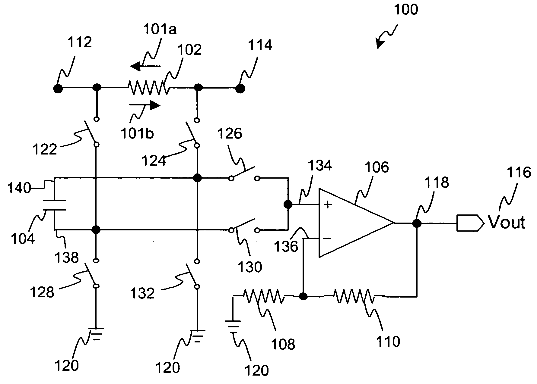
[0013] Referring first to FIG. 1, there is shown exemplary current sensing circuit 100 in accordance with one embodiment of the present invention. As discussed below, sensing circuit 100 is capable of accurately sensing bi-directional signals that flow through resistor 102 including current 101a from node 114 to node 112 and current 101b from node 112 to node 114 in an accurate and efficient manner.
[0014] By way of illustration, sensing circuit 100 is suitable for use in detecting charge current and discharge current in a portable device, such as a mobile communication device or a wireless handset device. A typical mobile communication device includes, among other things, a transceiver for transmitting and receiving an RF signal, and a mobile power source, such as a battery or fuel cell, coupled to the transceiver for supplying power to the transceiver. As such, sensing circuit 100 may be integrated into a mobile communication device to provide accurate battery capacity gauging and...
PUM
 Abstract
Description
Claims
Application Information