Digital camera with power supply for piezoelectric element and stroboscope circuit

Inactive Publication Date: 2006-01-03
RICOH KK
View PDF7 Cites 15 Cited by
  • Summary
  • Abstract
  • Description
  • Claims
  • Application Information

AI Technical Summary

Benefits of technology

[0006]It is an object thereof to present a digital camera capable of operating the piezoelectric element for displacing the imaging device, witho

Problems solved by technology

However, in the power source circuit for camera disclosed in Japanese Laid-open Patent No. 5-165080, a l

Method used


Image

  • Digital camera with power supply for piezoelectric element and stroboscope circuit
  • Digital camera with power supply for piezoelectric element and stroboscope circuit
  • Digital camera with power supply for piezoelectric element and stroboscope circuit

Examples


Embodiment Construction

[0029]Referring now to the accompanying drawings, preferred embodiments of the digital camera of the invention are described in detail below.

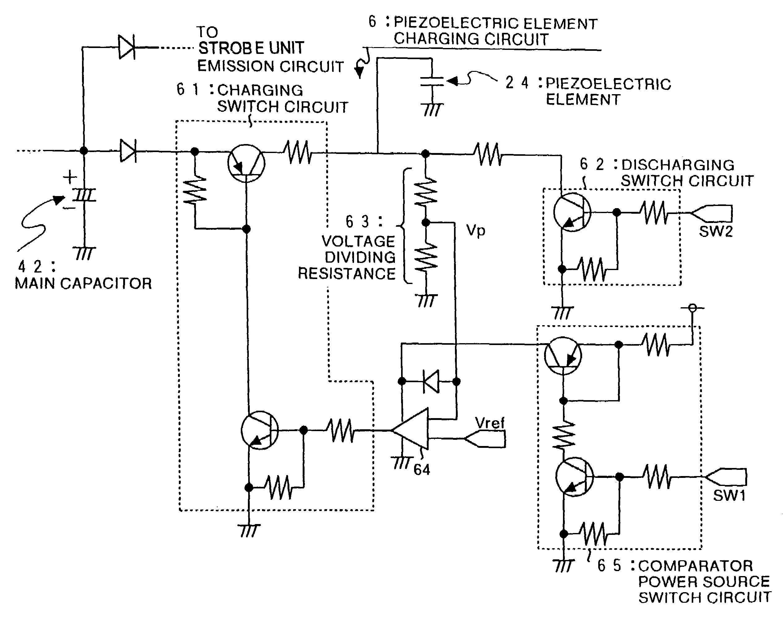
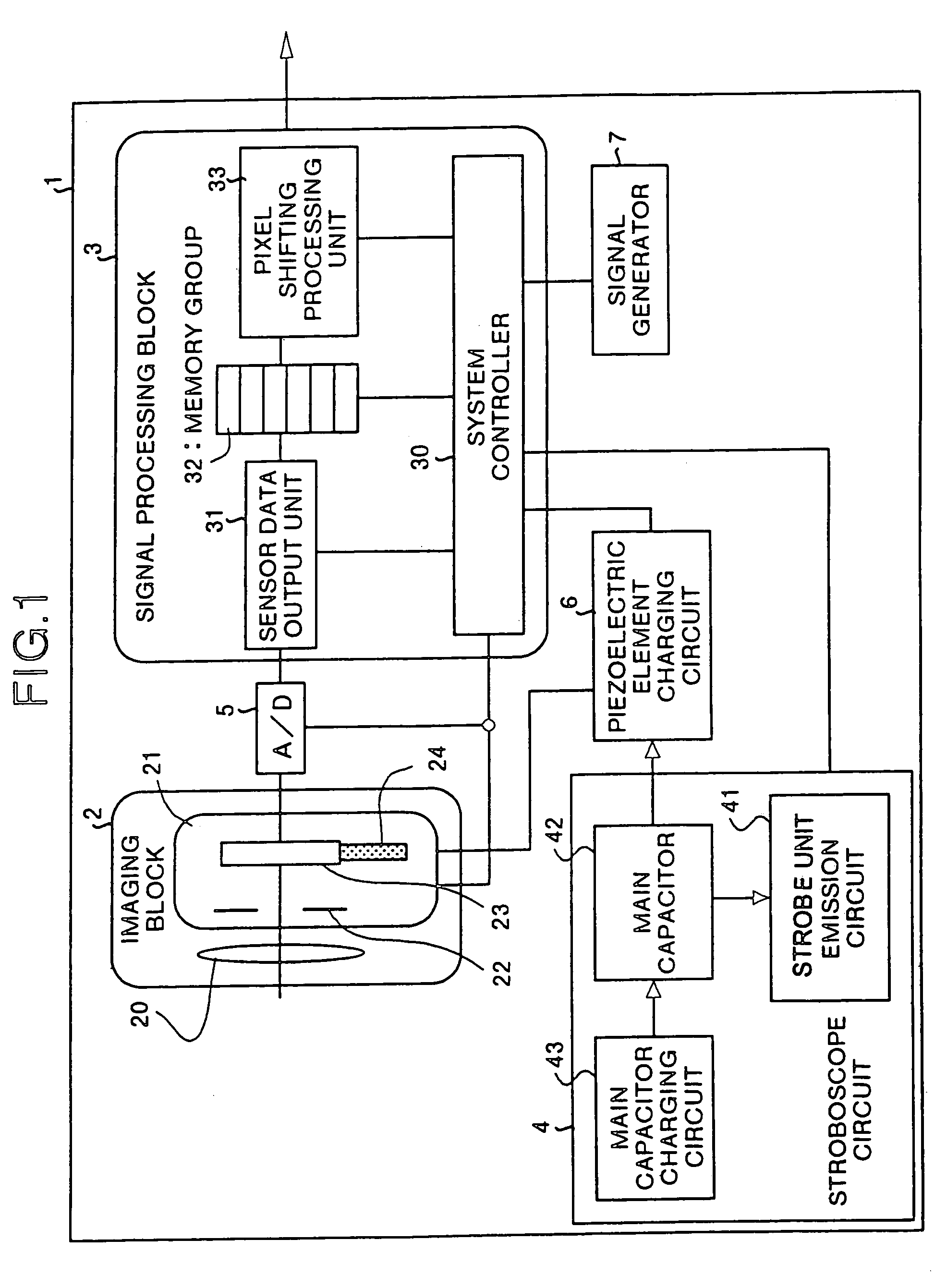
[0030]FIG. 1 is a block diagram of a digital camera of the invention. The digital camera 1 shown in FIG. 1 mainly comprises an imaging block 2 for taking a subject image to obtain analog image data, a signal processing block 3 for processing the digital image data digitized from the analog image data obtained in this imaging block 2, and issuing outside, and a stroboscope circuit 4.

[0031]In this digital camera 1, an A / D converter 5 for converting analog image data into digital data is provided between the imaging block 2 and the signal processing block 3, and the signal processing block 3 includes a signal generator 7 for generating a signal depending on the manipulation of mode switch or the like not shown, and issuing the signal to the signal processing block 3.

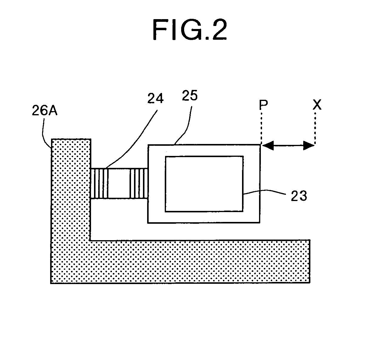
[0032]The imaging block 2 includes an optical lens 20, and an imaging unit 21 prov...


PUM


Abstract

To present a digital camera capable of operating a piezoelectric element without particularly preparing any boosting circuit inside the digital camera. In a digital camera for acquiring image data by taking a subject image, an imaging device for taking the subject image, and a piezoelectric element for displacing the imaging device are provided, and a main capacitor for stroboscope emission is used as the power supply source for the piezoelectric element.

Description

FIELD OF THE INVENTION[0001]The present invention relates to a digital camera, and more particularly to a digital camera having an imaging device displaced by a piezoelectric element.BACKGROUND OF THE INVENTION[0002]A higher image quality is demanded in the digital camera. To obtain an image of high quality, many pixels of a solid state imaging device are set, and a longer reading time is required. Accordingly, a pixel shifting technique is proposed recently in order to obtain a higher picture quality by a smaller number of pixels.[0003]Various techniques about power source circuit for an optical camera are disclosed. For example, a power source circuit for camera is disclosed in Japanese Laid-open Patent No. 5-165080, and in this power source circuit for camera incorporating an oscillating wave motor and a flash device, a first voltage to be applied to a piezoelectric element of the oscillating wave motor for operating the mechanism in the camera, and a second voltage for operating...

Claims


Application Information

Patent Timeline
IPC IPC(8): H04N5/225H04N5/228H04N1/00
CPCH04N1/00899H04N5/2354H04N3/1587H04N2101/00H04N25/48H04N23/74
Inventor YOSHIDA, AKIHIROKOSHIDA, NAOKI
Owner RICOH KK
Why Eureka
Try Eureka