
Digital camera, image signal processing method and recording medium for the same

Inactive Publication Date: 2006-01-03
MINOLTA CO LTD
View PDF4 Cites 24 Cited by
  • Summary
  • Abstract
  • Description
  • Claims
  • Application Information

AI Technical Summary

Benefits of technology

[0014]Accordingly, an object of the present invention is to provide a digital camera, and an image signal processing method and a recording medium for the same, with which it is possible, during shading correction, to reduce a load in digital image processing which is associated with a reduced amount of correction values, while preventing a deterioration in the quality of an image.
[0015]Another object of the present invention is to provide a digital camera, and an image signal processing method and a recording medium for the same, with which it is possible to easily correct a reduction in resolution in a peripheral area.
[0017]Another aspect of the present invention is to provide a digital camera comprising: an image pickup element for capturing an image; a correction value memory for storing predetermined resolution correction data each set in advance for each one of predetermined blocks which are obtained by dividing the entire area of the image captured by the image pickup element into at least a central area and a peripheral area; and an edge enhancer for edge-emphasizing the respective pixels based on the resolution correction data which are held in the correction value memory to thereby correct image field edge resolution reductions.
[0019]Still further aspect of the present invention is to provide an image signal processing method for a digital camera, comprising: in a condition that a predetermined correction value memory holds predetermined resolution correction data each set in advance for each one of predetermined blocks which are obtained by dividing the entire area of the image captured by the image pickup element into at least a central area and a peripheral area, executing edge-enhancement for the respective pixels based on the resolution correction data, to thereby correct image field edge resolution reductions.
[0021]Still further aspect of the present invention is to provide a recording medium which stores a program for correcting resolutions at the periphery of an image which is captured using a predetermined image pickup element of a digital camera, wherein the program is for executing a sequence in which, in a condition that predetermined resolution correction data each set in advance for each one of predetermined blocks which are obtained by dividing the entire area of the image captured by the image pickup element into at least a central area and a peripheral area are held in the digital camera, the respective pixels are edge-enhanced based on the held resolution correction data, to thereby correct image field edge resolution reductions.

Problems solved by technology

However, in this case, since correction values sharply change at contours of blocks, depending on the degree of data correction, a step on blocks becomes noticeable in a peripheral area of an image on a screen, which may deteriorate the quality of the image.
As the image field edge resolution reduction phenomenon has not been so far addressed by any digital image processing, the image shows increasingly blurred with a distance toward the peripheral area of the image from the central area of the image, and therefore, the quality of the image is poor.

Method used


Image

  • Digital camera, image signal processing method and recording medium for the same
  • Digital camera, image signal processing method and recording medium for the same
  • Digital camera, image signal processing method and recording medium for the same

Examples


Embodiment Construction

[0038]

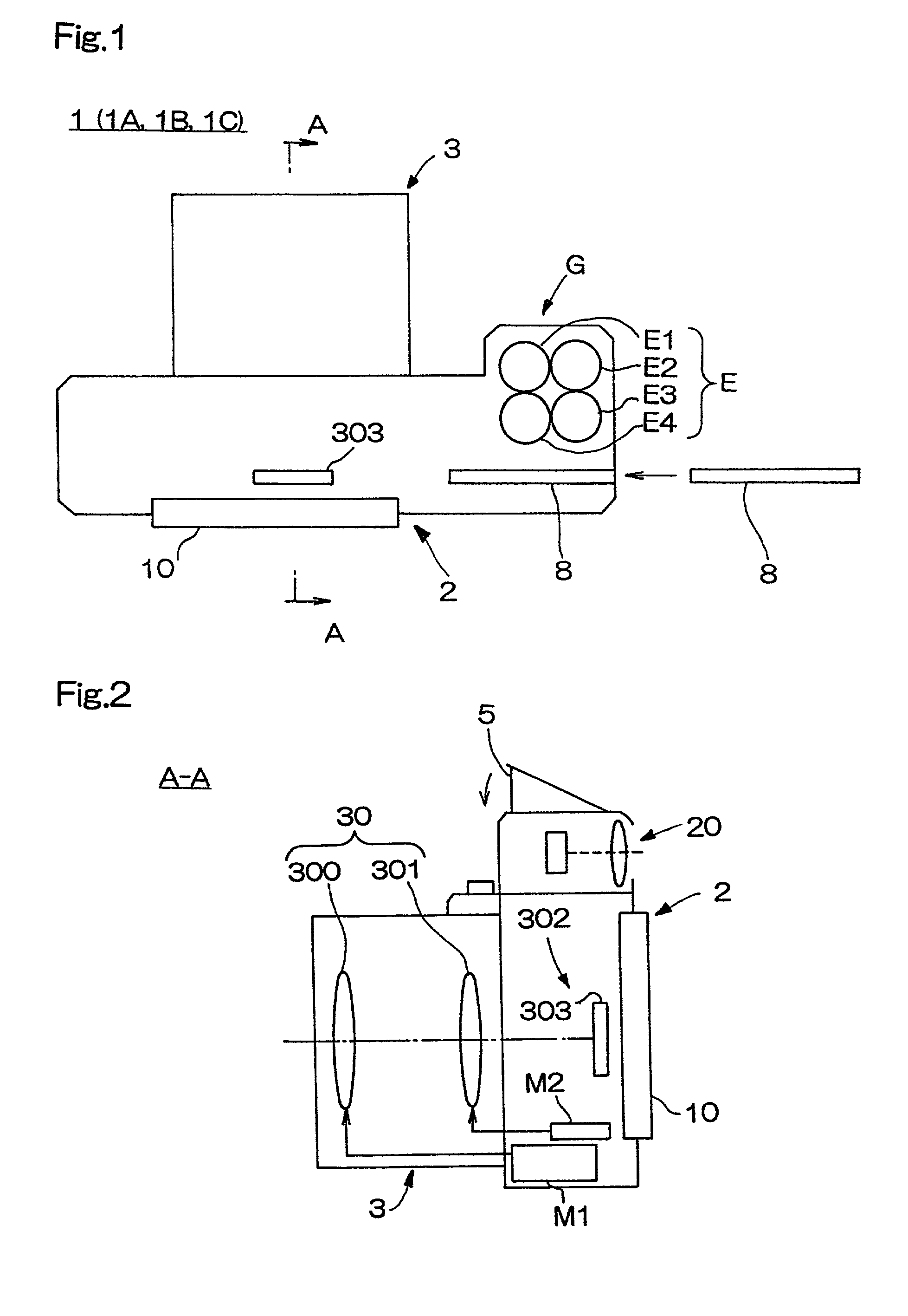
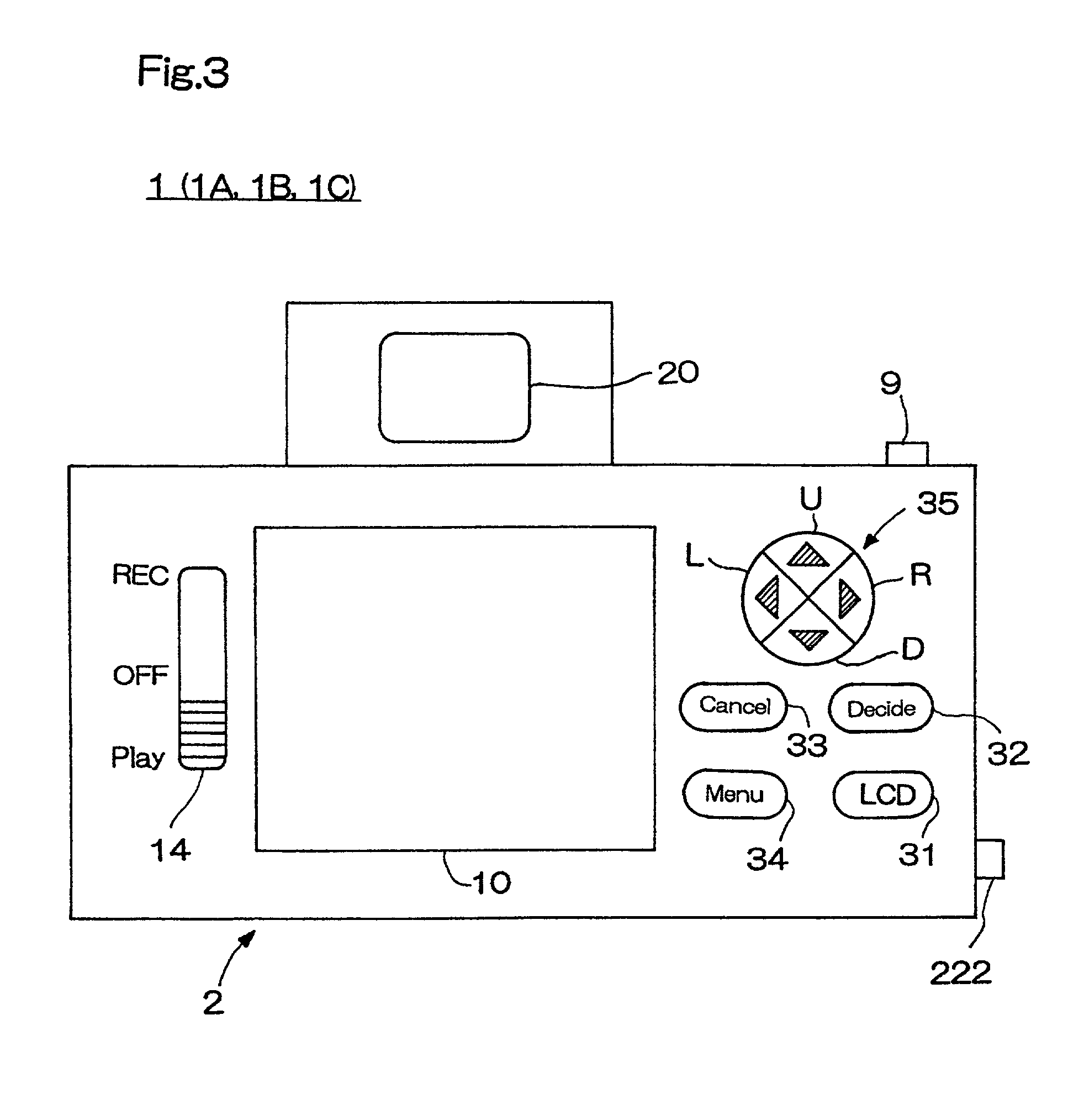
[0039]FIGS. 1 through 3 are drawings showing a basic structure of a digital camera 1, of which FIG. 1 is a plan view, FIG. 2 is a cross sectional view as viewed from the A—A position in FIG. 1, and FIG. 3 is a back view. These drawings are not necessarily in accordance with the third angle projection, but conceptually show an example of the basic structure of the digital camera 1.

[0040]As shown in these drawings, the digital camera 1 has an approximately rectangular shape, and as shown in FIG. 2, comprises an image pickup circuit 302 which has a CCD color sensor 303 at an appropriate position behind lens units 30 which form a taking lens. Further, the lens units 30 comprise a variator lens 300 and a compensator lens 301.

[0041]On the other hand, disposed inside a camera main unit 2 are a zoom motor M1 for changing a zoom rate of the variator lens 300 and a motor M2 for focusing by driving the compensator lens 301.

[0042]A grip portion G is formed as shown in FIG. 1 in a front su...


PUM


Abstract

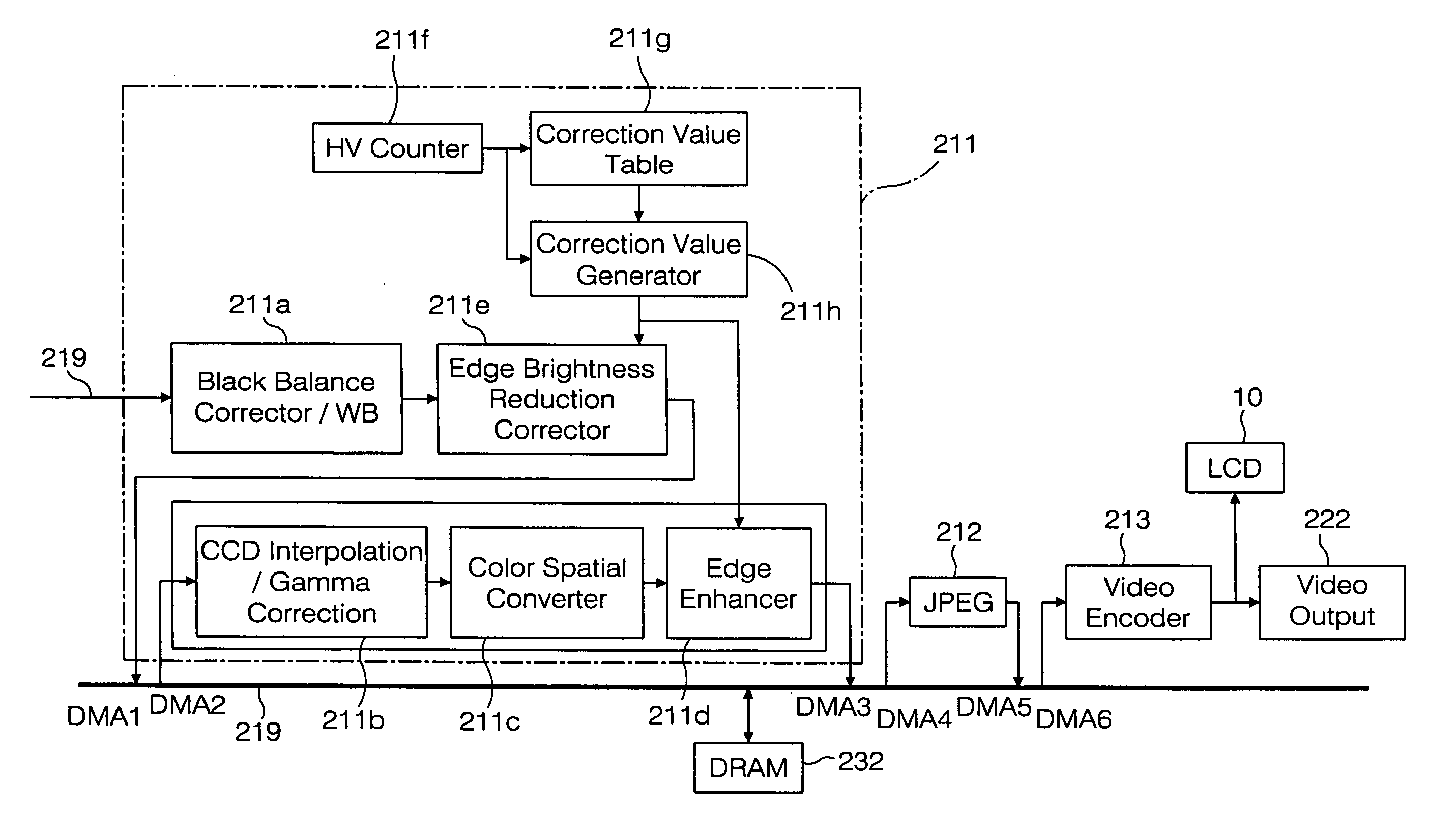
An image captured with a CCD is divided into blocks. Light amount correction data each set for each one of the blocks are read out from a correction value table 211g, a correction value generator 211h weights the light amount correction data in accordance with the positions of target pixels to thereby generate correction values for the respective target pixels, and image field edge brightness reduction correction is performed on the respective pixels based on the correction values. Since one piece of the data is set for each block, the volume of the data is small. This also prevents boundaries between the blocks from becoming noticeable.

Description

[0001]This application is based on application No. 2000-89093 filed in Japan, the content of which is hereby incorporated by reference.BACKGROUND OF THE INVENTION[0002]1. Field of the Invention[0003]The present invention relates to a digital camera which has a function of shading correction and / or edge enhancement, and an image signal processing method and a recording medium for the same.[0004]2. Description of the Prior Art[0005]In general, when an image is taken using a lens of a camera, a so-called image field edge brightness reduction phenomenon is created which is a (shading) phenomenon that the light amount decreases with a distance from a central point of the image to an edge of the image. In general, the smaller the f-number (=focal length / effective aperture) is, the larger the influence of the image field edge brightness reduction phenomenon is.[0006]In general, in the case of a silver halide film, since a change in output characteristic exhibits a curved profile as the amo...

Claims


Application Information

Patent Timeline
IPC IPC(8): H04N5/208G06K9/40H04N5/217H04N5/228H04N5/225H04N5/243H04N5/335H04N5/361H04N5/372H04N17/00H04N101/00
CPCH04N5/208H04N5/217H04N2101/00H04N17/002H04N23/81
Inventor NAKAMURA, KENJI
Owner MINOLTA CO LTD
Learn More