Mixer gain calibration method and apparatus

a technology of gain calibration and mixer, applied in the direction of electrical equipment, demodulation, radio transmission, etc., can solve the problems of affecting the signal integrity of the transmitter, the gain of the circuit elements, and the dependence on external circuit elements, etc., to achieve the effect of reducing the cost of the transmitter

Inactive Publication Date: 2006-01-03
MARVELL INT LTD
View PDF24 Cites 50 Cited by
  • Summary
  • Abstract
  • Description
  • Claims
  • Application Information

AI Technical Summary

Problems solved by technology

The gain of the circuit elements, which also depends upon the external circuit elements, cannot be easily compensated.
Poor mixer linearity can cause excessive corruption in the transmitter spectrum and degrade signal integrity of the transmitter.
These variations may adversely impact performance of the transceiver IC.
In use, power supply voltage variation and temperature variations of the environment may also adversely impact the performance of the transceiver IC.

Method used


Image

  • Mixer gain calibration method and apparatus
  • Mixer gain calibration method and apparatus
  • Mixer gain calibration method and apparatus

Examples


Embodiment Construction

[0046]The following description of the preferred embodiment(s) is merely exemplary in nature and is in no way intended to limit the invention, its application, or uses. For purposes of clarity, the same reference numbers will be used in the drawings to identify similar elements.

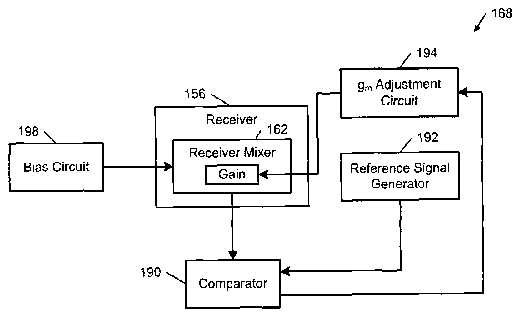
[0047]Referring now to FIG. 5A, a transceiver 150 according to the present invention includes a transmitter 154 and a receiver 156 with RF mixers 160 and 162, respectively. Gain calibration circuits 166 and 168 calibrate transmitter and receiver mixer gain, respectively. Calibration according to the present invention includes calibration during events such as power on, hardware reset, software reset and / or packet-based calibration during idle time between packets.

[0048]Referring now to FIG. 5B, the calibration circuit 166 includes a comparator 180, a reference signal generator 182 and a transconductance gm adjustment circuit 184. The reference signal generator 182 generates a reference current signal that is ...


PUM


Abstract

A gain calibration circuit for a radio frequency mixer in a wireless transceiver includes a reference signal generator that generates a reference signal. A comparator receives the reference signal and a second signal that is proportional to current flowing through the transmitter mixer and generates a difference signal. An adjustment circuit adjusts a transconductance gain of the mixer based on the difference signal. The adjustment circuit includes a plurality of binary weighted transconductance cells. The transconductance gain is calibrated during idle time between data packets or after power on, hardware reset, or software reset.

Description

FIELD OF THE INVENTION[0001]The present invention relates to gain calibration, and more particularly to gain calibration for radio frequency (RF) mixers that are implemented in wireless transceivers.BACKGROUND OF THE INVENTION[0002]Referring now to FIG. 1, a wireless transceiver 10 is shown and includes a transmitter 12 and a receiver 14. The wireless transceiver 10 may be used in a local area network (LAN) and may be attached to a Baseband Processor (BBP) and a Media Access Controller (MAC) in either a station or an Access Point (AP) configuration. A network interface card (NIC) is one of the various “STATION” configurations. The NIC can be connected to a networked device 16 such as a laptop computer, a personal digital assistant (PDA) or any other networked device. When the transceiver 10 is attached to an access point (AP) MAC, an AP is created. The AP provides network access for WLAN stations that are associated with the transceiver 10.[0003]The wireless transceiver 10 transmits...

Claims


Application Information

Patent Timeline
Patent Type & Authority Patents(United States)
IPC IPC(8): H04B1/06
CPCH03D7/1441H03G3/3042H03G3/3052H03D7/1491H03D7/1458H03D2200/0043H03D2200/0025
Inventor TSAI, KING CHUNTSE, LAWRENCECHIEN, GEORGE
Owner MARVELL INT LTD
Why Eureka
Try Eureka