Spring balance assembly

a technology of spring balance and assembly, which is applied in the direction of wing openers, multi-purpose tools, constructions, etc., can solve the problems of increasing material costs, requiring additional labor and time during assembly of spring balances, and limiting the use of conventional spring balance assemblies, so as to reduce the manufacturing time of window assembly, increase versatility, and reduce the effect of assembly tim

Inactive Publication Date: 2006-01-10
ASHLAND HARDWARE LLC
View PDF58 Cites 28 Cited by
  • Summary
  • Abstract
  • Description
  • Claims
  • Application Information

AI Technical Summary

Benefits of technology

[0011]The spring balance assembly of the present invention provides a number of significant advantages over conventional balance assemblies. Due to the configuration of the slots and the free portions, the springs are engaged by the pivot brake assembly without the use of any fasteners. As a result, assembly and disassembly of the spring balance assembly can be accomplished significantly faster. Thus, manufacturing times of the window assembly can be reduced since engagement of the springs to the pivot brake assembly involves only sliding the cooperatively dimensioned free portions into the appropriate slot. Consequently, the spring balance assembly of the present invention offers a multitude of cost-savings benefits as well as increased versatility, adjustability, and ease of assembly.

Problems solved by technology

Conventional balance assemblies exhibit limitations due to the manner in which the coil springs are connected to the pivot brake assembly.
The use of a fastener, including a threaded fastener, requires additional labor and time during assembly of the spring balance.
Furthermore, the fastener represents an additional part that increases material costs.

Method used


Image

  • Spring balance assembly
  • Spring balance assembly
  • Spring balance assembly

Examples


Embodiment Construction

[0025]While this invention is susceptible of embodiment in many different forms, there is shown in the drawings and will herein be described in detail preferred embodiments of the invention with the understanding that the present disclosure is to be considered as an exemplification of the principles of the invention and is not intended to limit the broad aspect of the invention to the embodiments illustrated.

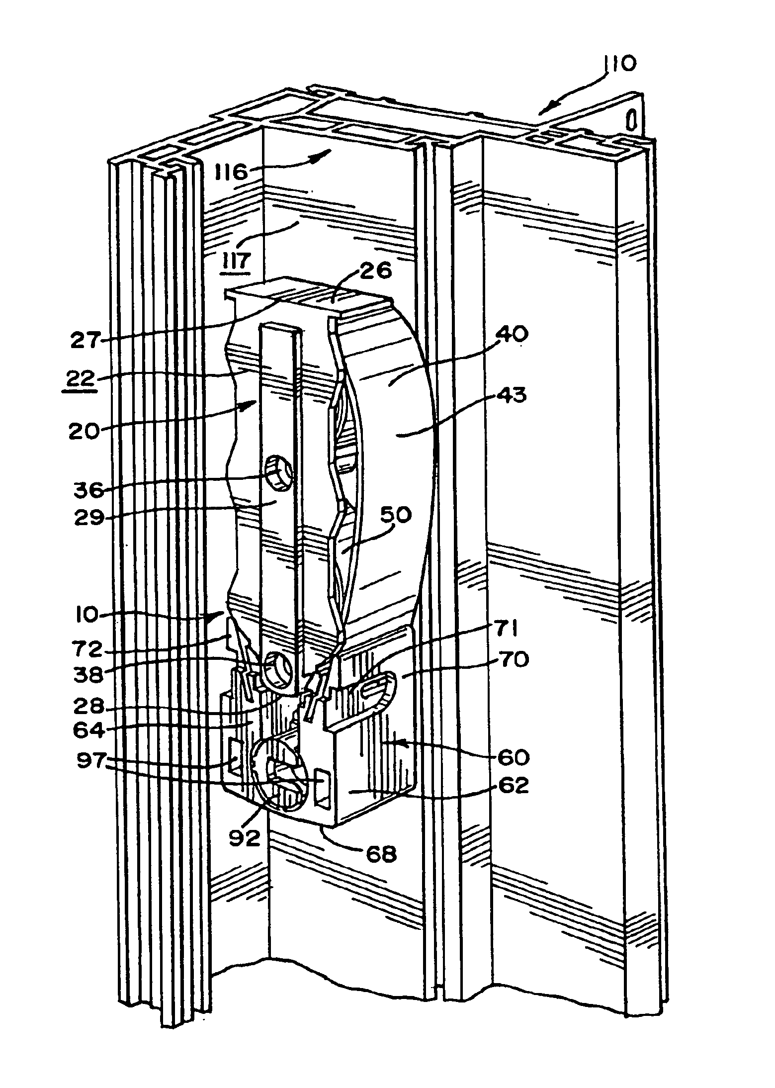
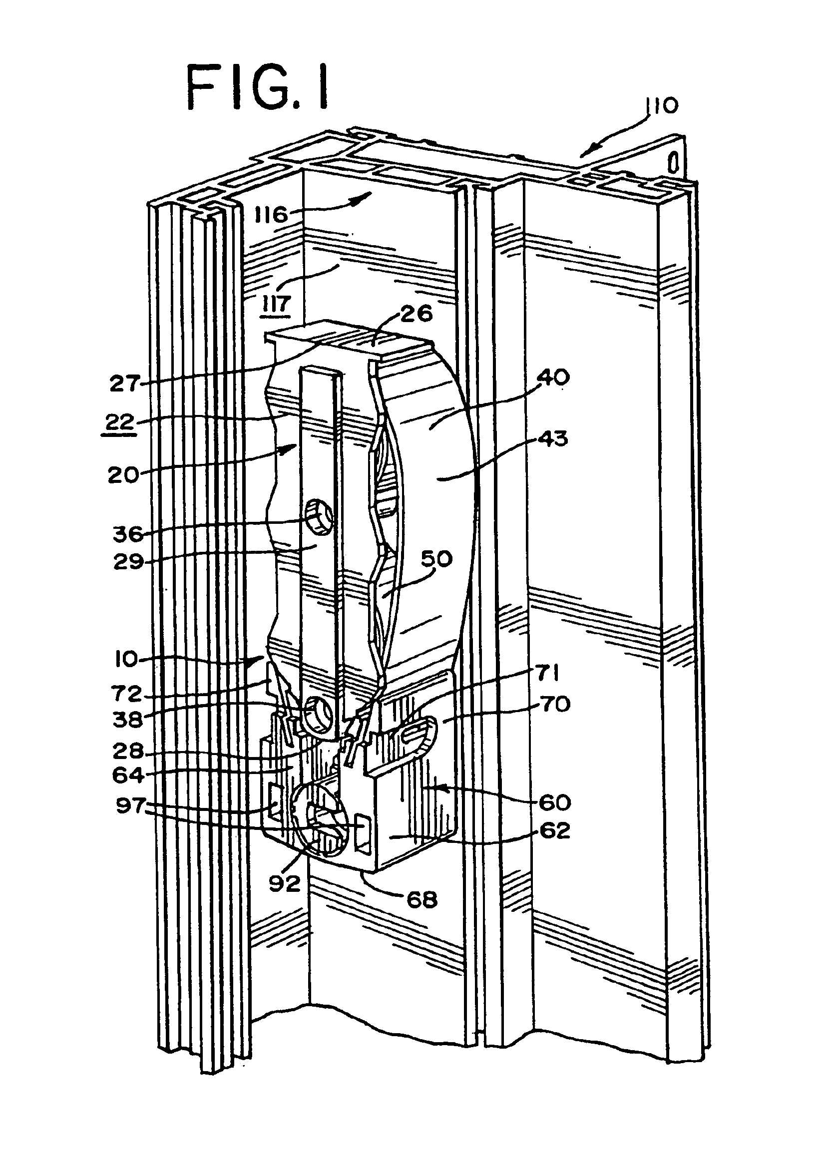
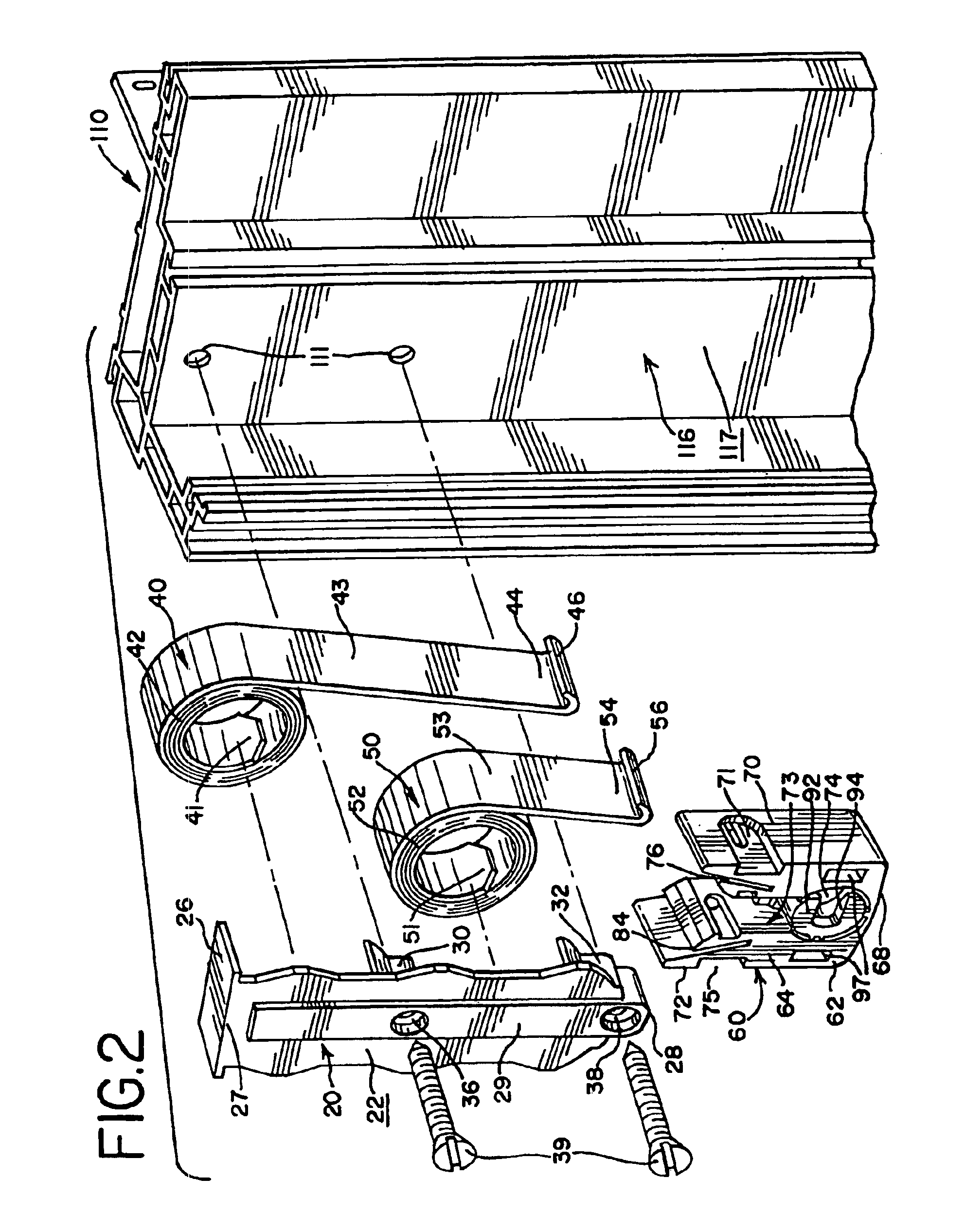
[0026]Referring to FIGS. 1, 11A, and 11B, a balance assembly 10 is affixed to a sash window assembly 100. The sash window assembly 100 shown in FIG. 11 is a double-hung window assembly having an upper pivotal sash window 102 and a lower pivotal sash window 104 in a master frame 110. In general terms, the master frame 110 includes a pair of opposed vertical guide rails 112 adapted to slidably guide the sash windows 102, 104. The master frame further includes a footer or lower horizontal element 114. The guide rail 112 defines an elongated channel 116 in which the spring balance a...


PUM


Abstract

The present invention provides a balance assembly (10) for use with a sash window assembly (104) slidable within a master frame (110). The balance assembly (10) generally includes a plate (20), at least one coil (40), and a shoe or pivot brake assembly (60). The plate (20) is adapted to be attached to the master frame (110). The spring (40) has a coiled portion (42), an intermediate portion (43), and a free portion (44). The coiled portion (42) of the spring (40) is rotatably supported by a support member (30) extending from the plate (20). The free portion (44) of the spring (40) has a curved configuration with a curved end (46). The pivot brake assembly (60) has at least one slot (76) adapted to receive and retain the free portion (44) of the spring (40). The slot (76) defines a protrusion (83) that engages the free portion (44).

Description

TECHNICAL FIELD[0001]The present invention relates to a spring balance assembly for a sash window. More specifically, the present invention relates to a spring balance assembly having a coil spring that is secured to a pivot brake assembly without the use of a fastener.BACKGROUND OF THE INVENTION[0002]Sash windows disposed within a master frame are quite common. Generally, the master frame includes a pair of opposed vertical guide rails, an upper horizontal member or header, and a lower horizontal member or base. The guide rails are designed to slidingly guide at least one sash window within the master frame. Double hung sash windows have an upper sash window and a lower sash window. The guide rails of the master frame define an elongated channel. To counterbalance the sash window during movement of the window, a spring balance assembly is affixed to the master frame in the elongated channel and connected to the sash window.[0003]One conventional balance assembly includes a plate, o...

Claims


Application Information

Patent Timeline
Patent Type & Authority Patents(United States)
IPC IPC(8): E05F1/00E05C17/64E05D15/22E05F1/16
CPCE05D13/08E05D13/1276E05D15/22Y10T16/64E05Y2900/148
Inventor PETTIT, DEAN
Owner ASHLAND HARDWARE LLC
Why Eureka
Try Eureka