Specimen observation method in atomic force microscopy and atomic force microscope

a technology of atomic force microscopy and microscope, applied in the direction of mechanical measurement arrangement, mechanical roughness/irregularity measurement, instruments, etc., can solve the problem of long time-consuming visualization owing to mapping of resonance frequency and q factor

Inactive Publication Date: 2006-01-10
JEOL LTD
View PDF8 Cites 21 Cited by
  • Summary
  • Abstract
  • Description
  • Claims
  • Application Information

AI Technical Summary

Problems solved by technology

Therefore, visualization owing to mapping of resonance frequencies and Q factors takes a long time.

Method used


Image

  • Specimen observation method in atomic force microscopy and atomic force microscope
  • Specimen observation method in atomic force microscopy and atomic force microscope
  • Specimen observation method in atomic force microscopy and atomic force microscope

Examples


Embodiment Construction

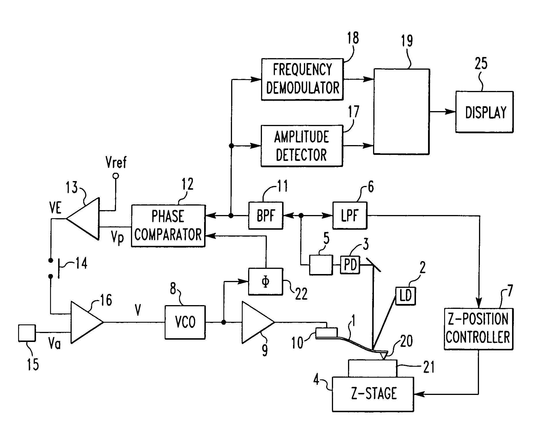
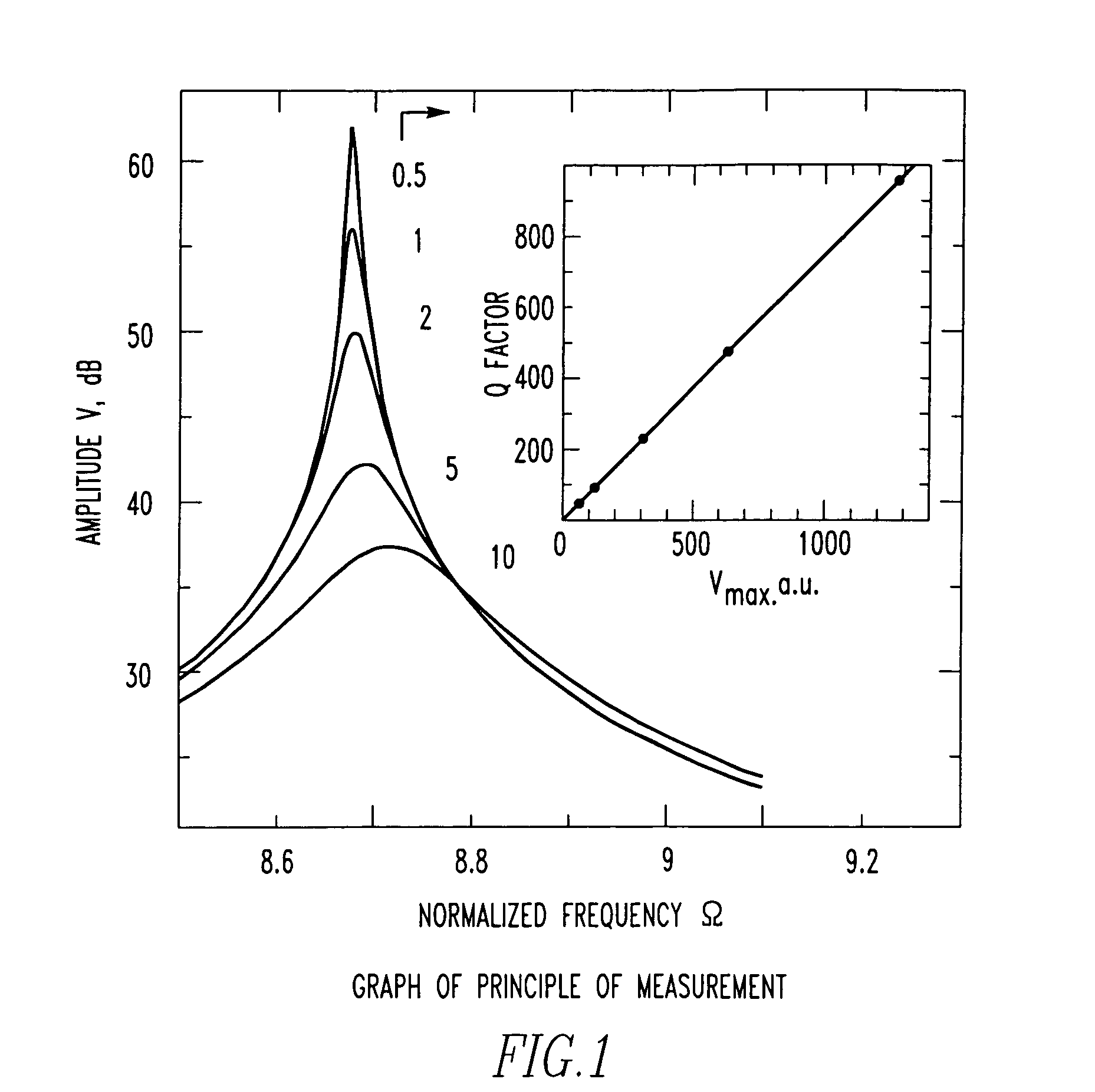
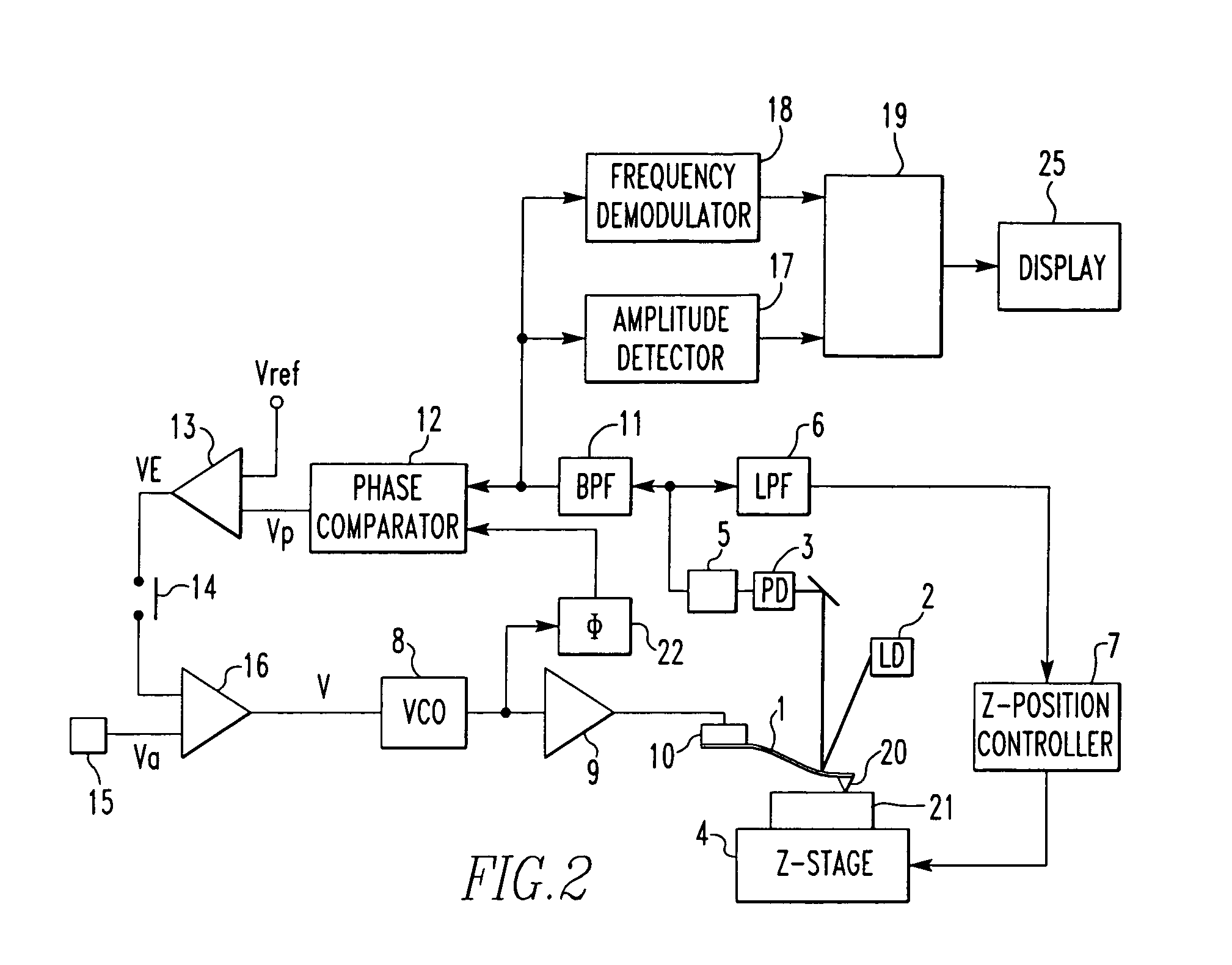
[0013]The amplitude of vibration of a cantilever is in proportion to the Q factor when the vibration is in resonance. It is the object of the present invention to provide a Q factor-measuring method and a method of visualizing the distribution of the Q factor. These methods are characterized in that the Q factor is calculated from the amplitude of the vibration using a calibration curve prepared separately after measuring the amplitude of the vibration in resonance. No frequency sweeping is necessary here to measure the Q factor in atomic fore microscopy, unlike the prior art method. Consequently, the measurement is performed quickly. Concomitantly, the resonance frequency can be measured. Detail analysis of material characteristics is enabled by simultaneous measurement of resonance frequency and Q factor.

[0014]The effectiveness of the principle of the present invention is next theoretically demonstrated. It is known that where the waveform of vibration of a cantilever excited by i...


PUM


Abstract

A method and apparatus for observing a specimen in atomic force microscopy with a vibrating cantilever maintained in resonance while a probe attached to the cantilever is maintained in contact with the specimen. The Q factor of the cantilever is determined based upon the detected amplitude.

Description

BACKGROUND OF THE INVENTION[0001]1. Field of the Invention[0002]The present invention relates to a method that is used to observe a specimen in atomic force microscopy (AFM) and adapted for evaluation of physical properties of a specimen. The invention also relates to an atomic force microscope implementing this method.[0003]2. Description of Related Art[0004]Ultrasonic atomic force microscopy has been developed as a technique for evaluating the contact elasticity of the portion of a specimen surface contacted with a probe, from the resonance frequency of the flexural vibration of the cantilever of an atomic force microscope (AFM) operating in contact mode (K. Yamanaka and S. Nakano, Jpn. J Appl. Phys., Vol. 35 (1996), pages 3787–3792). This method has the feature that it can evaluate the contact elasticity of a stiff sample using a softer cantilever than is used in the presently commercially available contact elasticity evaluation technique of force modulation mode. This method is ...

Claims


Application Information

Patent Timeline
Patent Type & Authority Patents(United States)
IPC IPC(8): G01B5/28G01B21/30G01Q60/24G01Q60/34
CPCB82Y35/00G01Q60/32G01Q40/00Y10S977/85
Inventor YAMANAKA, KAZUSHINAKAMOTO, KEIICHI
Owner JEOL LTD
Why Eureka
Try Eureka