Variable drag projectile stabilizer for limiting the flight range of a training projectile

a projectile stabilizer and variable drag technology, applied in the field of training projectiles, can solve the problems of severely restricting further flight, increase in aerodynamic drag, etc., and achieve the effect of altering the aerodynamic characteristics of the projectil

Inactive Publication Date: 2006-01-10
UNITED STATES OF AMERICA THE AS REPRESENTED BY THE SEC OF THE ARMY
View PDF4 Cites 11 Cited by
  • Summary
  • Abstract
  • Description
  • Claims
  • Application Information

AI Technical Summary

Benefits of technology

[0012]The present invention satisfies this need, and presents a limited range training projectile stabilizer for a kinetic energy training projectile. The variable drag projectile stabilizer is a passive device that applies supersonic flow phenomena to alter the aerodynamic characteristics of a projectile while in free flight. The variable drag projectile stabilizer enables a training projectile to follow the trajectory path of an armor piercing discarding sabot (APDS) kinetic energy projectile for an initial 3 km of flight while limiting the range of the training projectile to 8 km.

Problems solved by technology

The ensuing rapid increase in aerodynamic drag severely limits further flight.

Method used


Image

  • Variable drag projectile stabilizer for limiting the flight range of a training projectile
  • Variable drag projectile stabilizer for limiting the flight range of a training projectile
  • Variable drag projectile stabilizer for limiting the flight range of a training projectile

Examples


Embodiment Construction

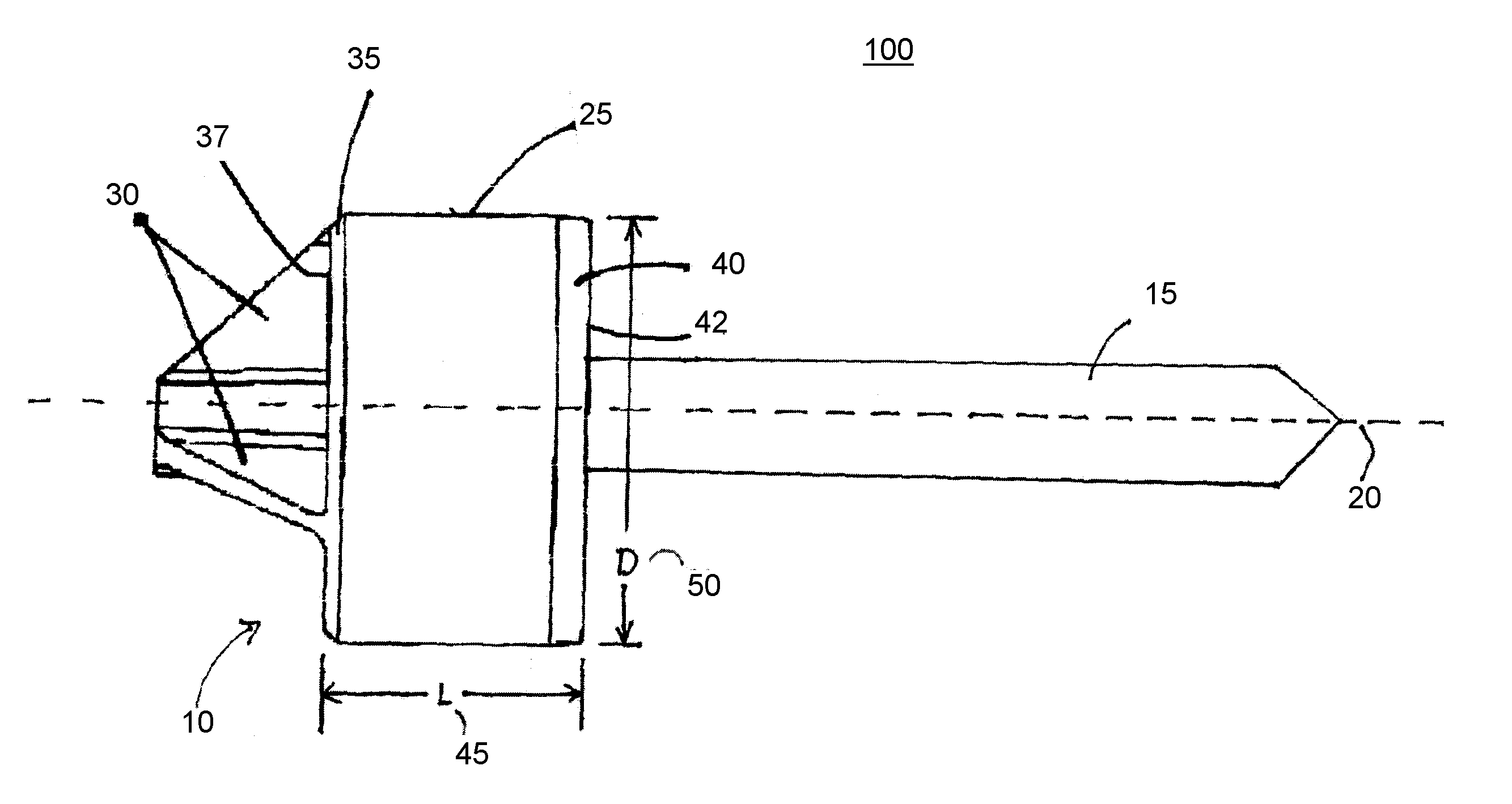
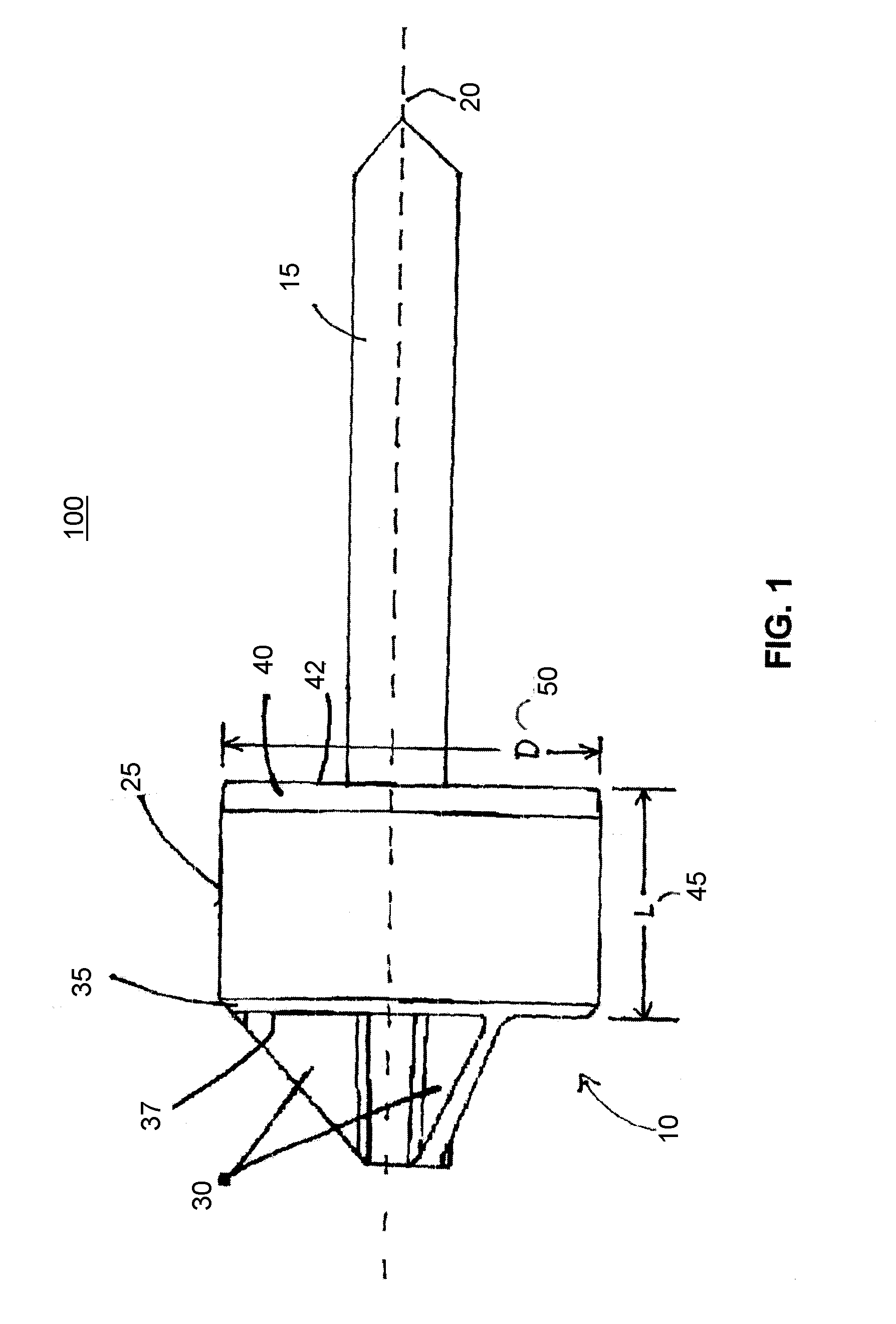
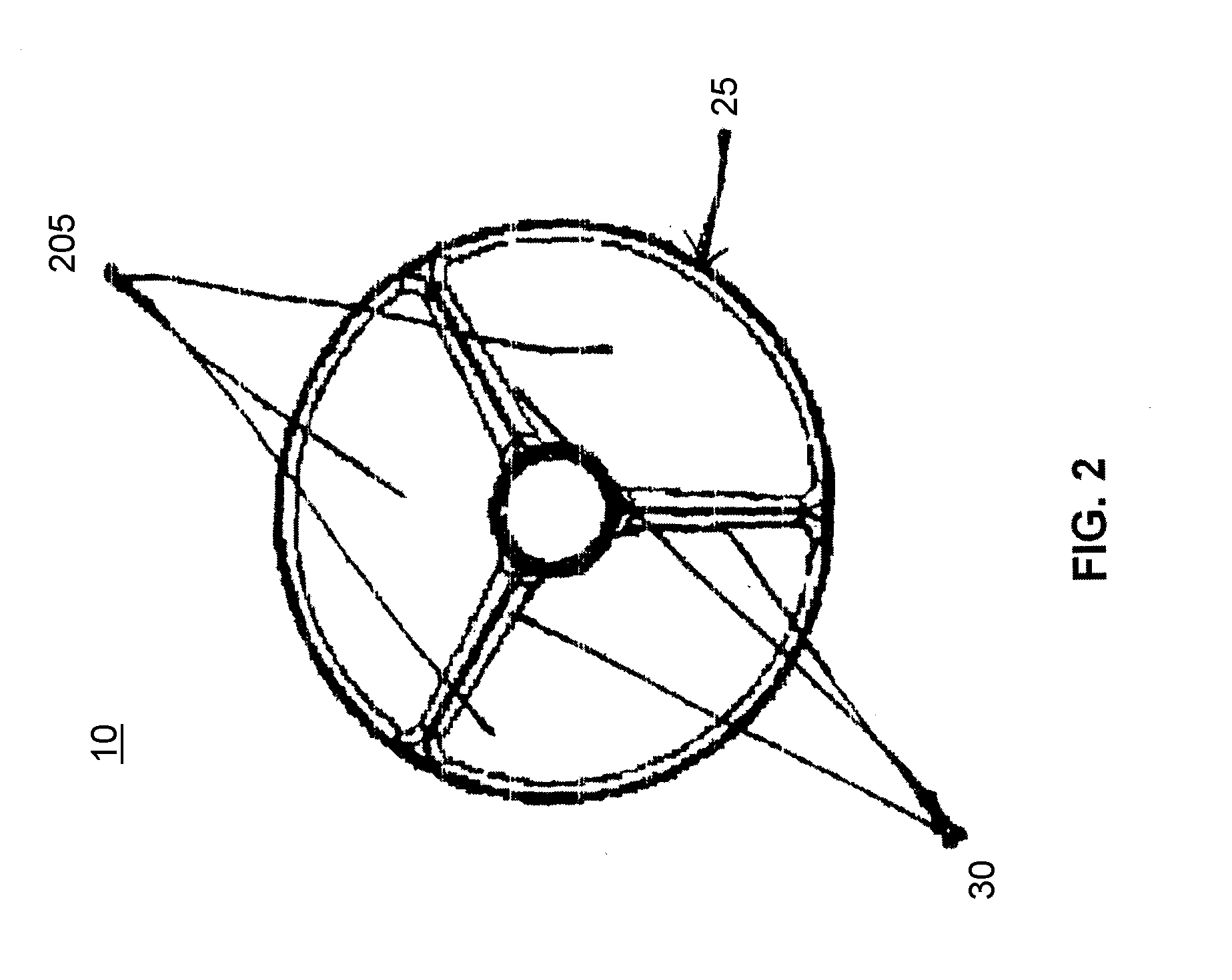
[0031]FIG. 1 illustrates an exemplary training projectile 100 comprising a variable drag projectile stabilizer 10 that utilizes supersonic airflow to change the aerodynamics of the training projectile 100 during flight. The variable drag projectile stabilizer 10 (also referenced herein as stabilizer 10) is mounted on a tail end of a cone-tipped cylindrical rod 15. Stabilizer 10 is cylindrical with respect to axis 20. Stabilizer 10 comprises a cowling 25 supported by struts 30. The cowling 25 and the struts 30 provide tail lift and ensure a stable flight path of the training projectile 100.

[0032]Struts 30 extend beyond the trailing edge 37 of cowling 25 to support a setback load or force experienced by cowling 25 during a gun launch of the training projectile 100. Cowling 25 comprises a trailing edge bevel 35, a leading edge bevel 40 and an angled interior surface 415. The cowling 25 and struts 30 are typically made of a lightweight metal, such as aluminum or titanium. However, compo...


PUM


Abstract

A variable drag projectile stabilizer is utilized by a training projectile to match the trajectory of a tactical projectile for up to 3 km while having a range limitation of 8 km. The stabilizer applies supersonic flow phenomena to alter the aerodynamic characteristics of a training projectile while in free flight to fulfill this requirement. The stabilizer uses a cowling supported by struts to provide tail lift and ensure a stable flight path. Supersonic flow is established through ducts formed by the cowling and struts when launched from a weapon. The flow remains supersonic until the projectile reaches the desired range but then quickly becomes subsonic (choked) due to shock waves emanating from interior angles in the ducts. The geometry of the ducts can be designed to create different shock wave patterns within the ducts. The variance of leading edge location, leading edge angle, cowling intake angle, and flight Mach number influences the shock patterns within the ducts and consequently, the range of the projectile.

Description

FEDERAL RESEARCH STATEMENT[0001]The inventions described herein may be manufactured, used and licensed by or for the U.S. Government for U.S. Government purposes.BACKGROUND OF INVENTION[0002]Field of the Invention[0003]The present invention relates to a tank training projectile. More particularly this invention pertains to a training projectile with an effective range that can be regulated by means of a variable drag projectile stabilizer. In specific, the present invention utilizes supersonic airflow to change the aerodynamics of the training projectile during flight, thus matching the flight characteristics of a corresponding service ammunition during the initial part of the flight while not exceeding a predetermined range of the training projectile.BACKGROUND OF THE INVENTION[0004]The Army has an on-going need for long-range kinetic energy projectiles for use in artillery and tank training. For effective training, ballistic characteristics of a training munition should match that...

Claims


Application Information

Patent Timeline
Patent Type & Authority Patents(United States)
IPC IPC(8): F42B8/00
CPCF42B10/48F42B10/02
Inventor MALEJKO, GREGORYVELLA, ANTHONYSCHEPER, ERIC P.DONADIO, PHILIP M.
Owner UNITED STATES OF AMERICA THE AS REPRESENTED BY THE SEC OF THE ARMY
Why Eureka
Try Eureka