

Elevator drive belt
a technology of drive belt and elevator, which is applied in the direction of elevators, conveyors, transportation and packaging, etc., can solve the problems of unsafe drive of the cage, control failure, and insufficient transmission of the winding machine, so as to improve the grip force and the effect of abrasion resistan
- Summary
- Abstract
- Description
- Claims
- Application Information
AI Technical Summary
Benefits of technology
Problems solved by technology
Method used
Image

Examples
embodiment 1
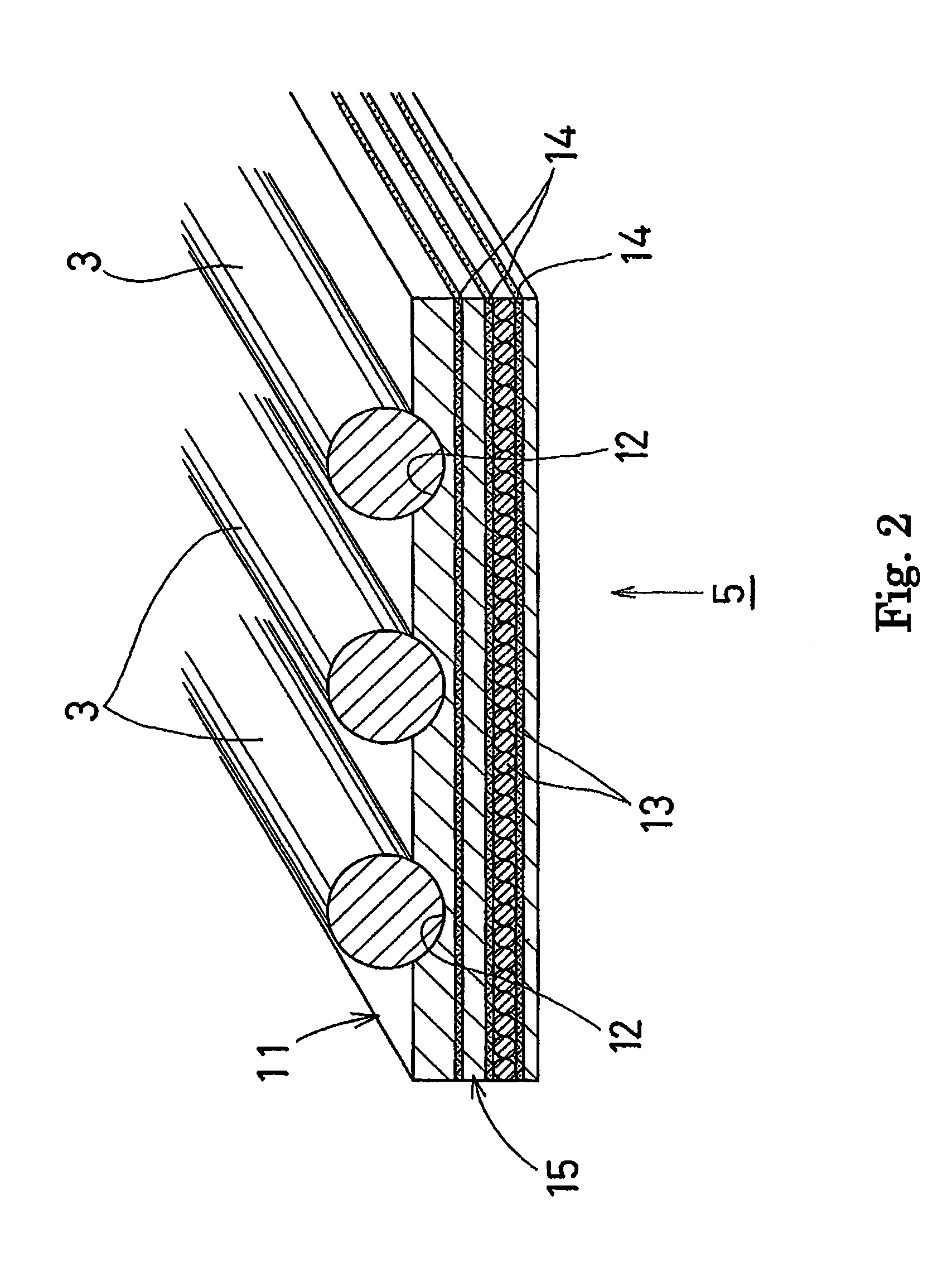
[0051]The surface layer 11 was made of chloroprene rubber with a hardness of 63 degrees, and the intermediate layer 15 under the surface layer 11 was also made of chloroprene rubber with a hardness of 63 degrees. As the result, the load was 104 kgf.
embodiment 2
[0052]The surface layer 11 was made of chloroprene rubber with a hardness of 63 degrees, and the intermediate layer 15 under the surface layer 11 was also made of chloroprene rubber, but with a hardness of 80 degrees. As the result, the load was 120 kgf.
embodiment 3
[0053]The surface layer 11 was made of chloroprene rubber with a hardness of 80 degrees, and the intermediate layer 15 under the surface layer 11 was also made of chloroprene rubber with a hardness of 80 degrees. As the result, the load was 98 kgf.
PUM
 Abstract
Description
Claims
Application Information