Aviation tire

a technology for aircraft tires and tires, applied in the field of tires, can solve the problems of significant frictional forces, shorten the useful life of tires, and the difference between the velocity of the wheel and the velocity of the surface, and achieve the effect of reducing the wear of aviation tires

Active Publication Date: 2006-01-10
NORDQUIST THOMAS D
View PDF6 Cites 25 Cited by
  • Summary
  • Abstract
  • Description
  • Claims
  • Application Information

AI Technical Summary

Benefits of technology

[0005]In light of the forgoing, it is an object of the present invention to reduce aviation tire wear.
[0006]It is an object of the present invention to provide a tire adapted to rotate in the direction of the flight of the aircraft, on which it is mounted, to reduce the frictional forces that occur upon impact of the tire on a landing surface.

Problems solved by technology

The typically large difference between the velocity of the wheel and velocity of the surface on which the plane is landing generates significant frictional forces between the surface of the wheel's tire and the landing surface.
Repeated flatspotting greatly shortens the useful life of the tire.
As a result, the frictional forces coupled with the downward force of the plane results in a great amount of wear and tear on the tire.
This wear requires frequent replacement of the tires and increases the amount of downtime for the plane.

Method used


Image

  • Aviation tire
  • Aviation tire
  • Aviation tire

Examples


Embodiment Construction

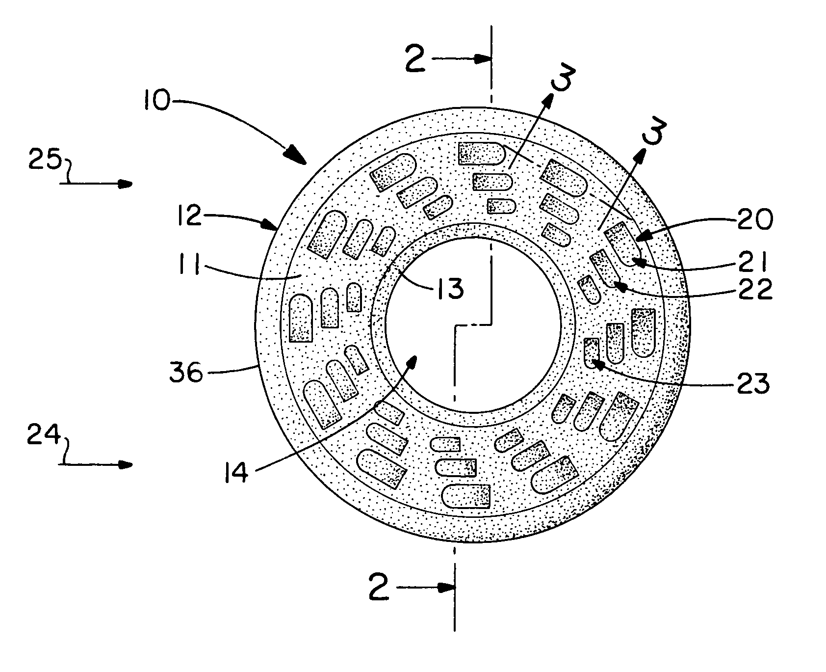
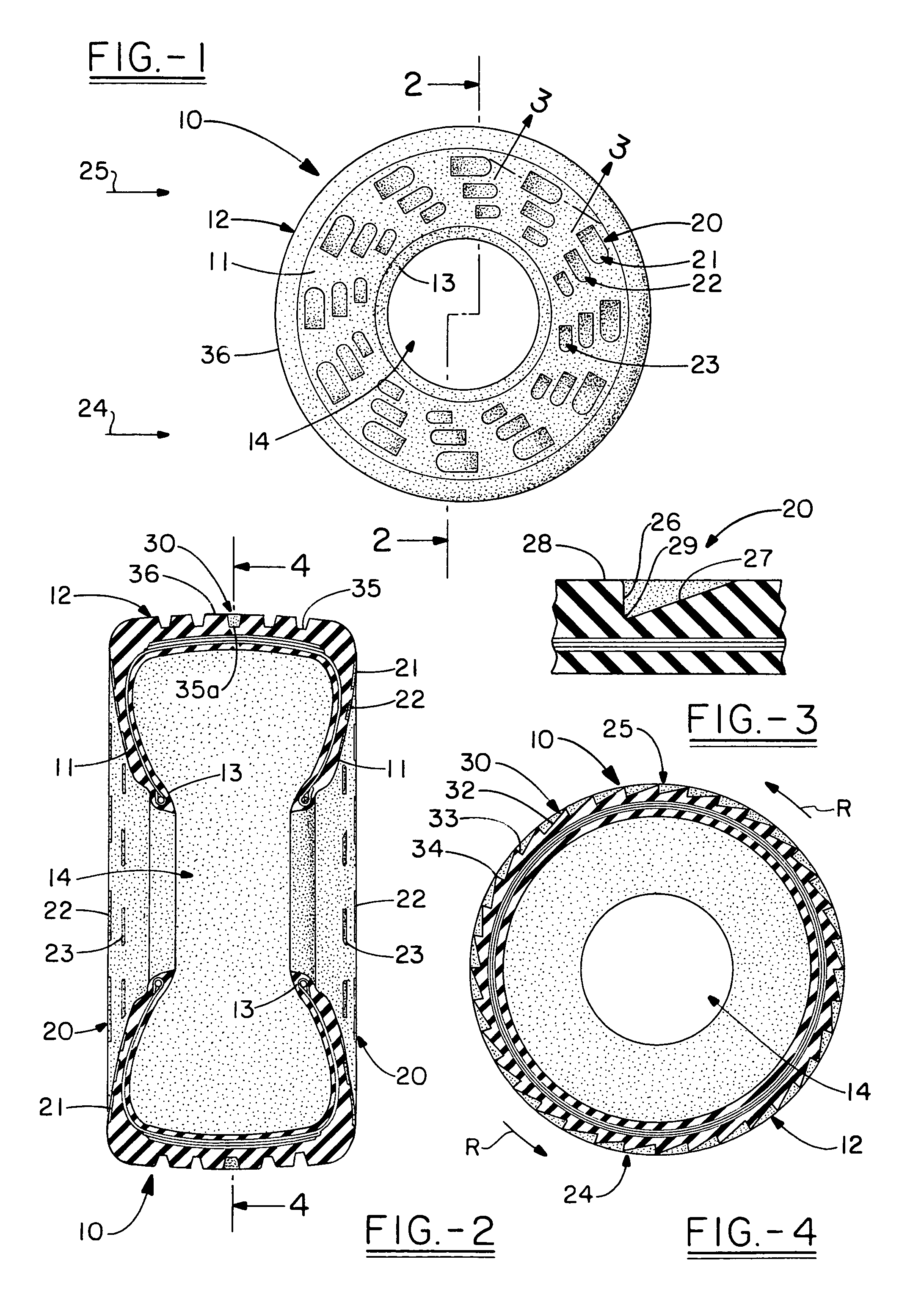
[0019]A tire according to the concepts of the present invention is generally indicated by the numeral 10 in the accompanying drawings. Tire 10 includes sidewalls 11 and a tread portion, generally indicated by the numeral 12, that spans the sidewalls 11 at the radial outer extremity of the tire 10. A bead ring 13 is formed on the radial inner extremity of the tire 10 and defines a central opening 14 in which a rim (not shown) is received. To this extent, the tire 10 is of a conventional construction and may be manufactured according to methods known in the art.

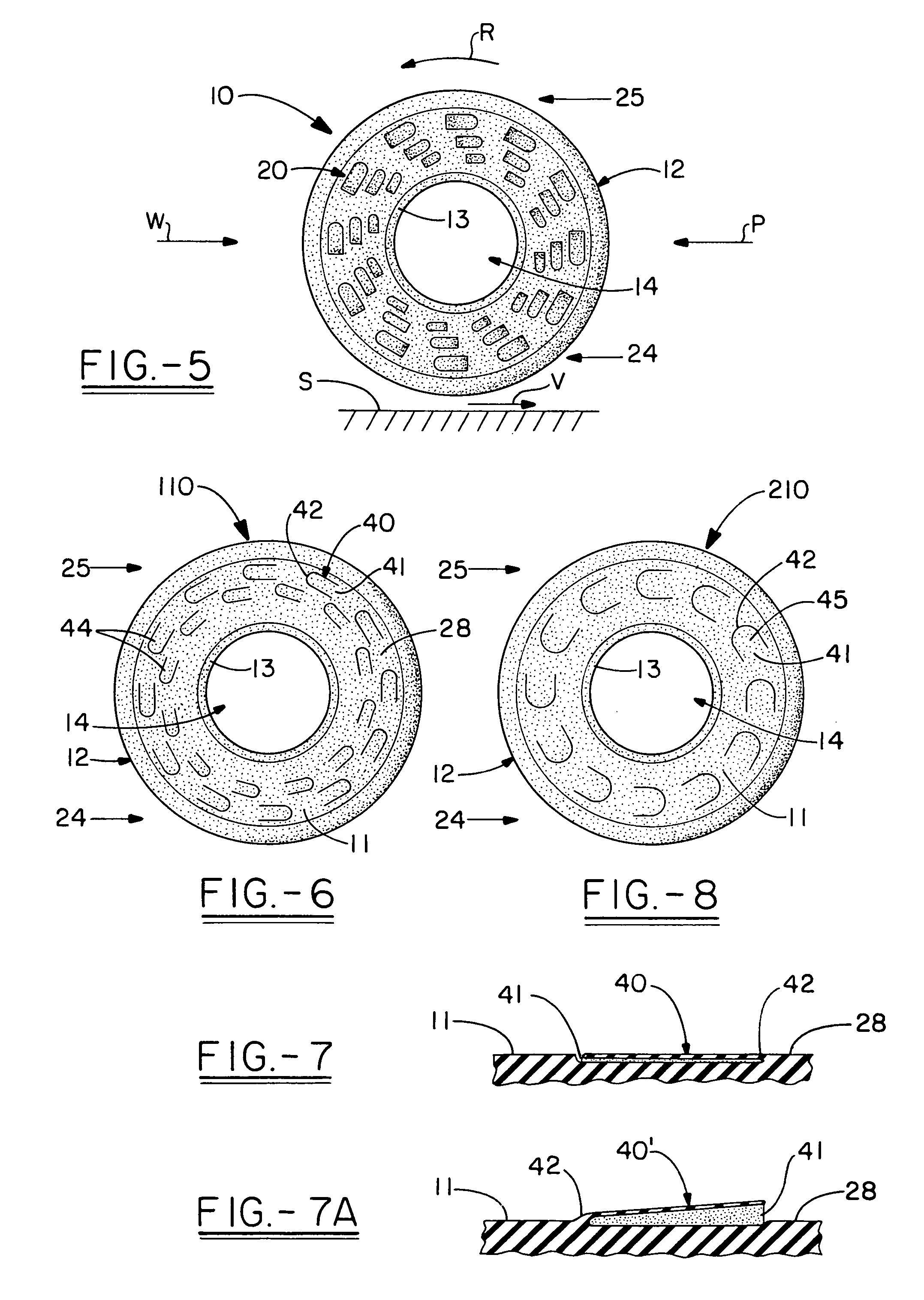
[0020]As best shown in FIG. 5, when the tire 10 is in flight it travels in the direction of the plane, as indicated by the arrow P, and faces wind flow, generated by the movement of the plane, generally opposite the plane direction P and indicated by the wind direction arrow W. To reduce the relative velocity between the tire 10 and the landing surface S at impact, it is desirable to cause the tire 10 to rotate forwardly relati...


PUM


Abstract

An aviation tire including, a pair of side walls, the side walls having an outer surface, a tread portion spanning a radial outer extremity of the side walls, and a rotating assembly formed on the side wall or the tread portion, the rotating assembly having an increased resistance to wind when located at a lowermost portion of the tire.

Description

TECHNICAL FIELD[0001]The present invention relates to tires. More particularly, the present invention relates to a tire used in connection with aircraft landing gear. Most particularly, the present invention relates to an aviation tire that is adapted to rotate in the direction of the flight of the aircraft to reduce frictional forces at touchdown of the tires.BACKGROUND OF THE INVENTION[0002]As is well known, planes typically travel at significant speeds at the point of landing. To accommodate these speeds, wheels are provided on the aircraft landing gear such that the aircraft continues to move after the plane lands on the runway. Braking forces may then be applied either to the wheels or by means of jet reversers to bring the plane to a stop.[0003]Considering the wheels in more detail, when in flight, the wheels are in a moving reference frame. In particular, the wheels have a velocity equal to the velocity of the plane just prior to impact relative to the surface on which the pl...

Claims


Application Information

Patent Timeline
Patent Type & Authority Patents(United States)
IPC IPC(8): B64C25/32
CPCB64C25/40B60C13/02B60C2200/02
Inventor NORDQUIST, THOMAS D.
Owner NORDQUIST THOMAS D
Why Eureka
Try Eureka