Axial sealing structure of scroll compressor

a scroll compressor and sealing structure technology, which is applied in the direction of liquid fuel engines, machines/engines, rotary piston liquid engines, etc., can solve the problems of axial sealing structure still existing in the conventional way, waste of resources, and laborious and complicated manufacturing procedures, so as to reduce the difficulty of the assembly procedure of the scroll compressor, improve product quality, and reduce production costs

Inactive Publication Date: 2006-01-10
NO 31 1 LANE 169 KANGNING ST +1
View PDF9 Cites 34 Cited by
  • Summary
  • Abstract
  • Description
  • Claims
  • Application Information

AI Technical Summary

Benefits of technology

[0005]The present invention provides an axial sealing structure of a scroll compressor. Two seal elements are respectively secured to a floating seal member and a fixed scroll. The present invention is capable of both simplifying and reducing the difficulty of the assembling procedure of the scroll compressor. A scroll compressor utilizing the present invention has a better product quality and a lower production cost.
[0006]The axial sealing structure of a scroll compressor of the present invention has the floating seal member disposed between a partition and the top of the fixed scroll. An intermediate pressure room is formed between the floating seal member and the fixed scroll to force the fixed scroll to closely attach an orbiting scroll, so as to enhance the volume efficiency of the compressor.
[0007]The axial sealing structure of a scroll compressor of the present invention guides the intermediate pressure working fluid into the intermediate pressure room to force the fixed scroll to move downward such that the axial force and biasing torque applied to the fixed scroll during compression are overcome. The lifetime of the scroll compressor is effectively extended.

Problems solved by technology

The axial, radial and tangential forces cause leakage from the end panels or the side surfaces of the wraps.
However, there is a problem still existing in the conventional axial sealing structure.
In summary, although the conventional art can produce a scroll compressor with a floating seal member, the manufacture procedure thereof is tedious and complicated.
The conventional art has to consume a longer labor hours to produce a scroll compressor with a floating seal.
The fabrication cost of the conventional art is inevitably high.

Method used


Image

  • Axial sealing structure of scroll compressor
  • Axial sealing structure of scroll compressor
  • Axial sealing structure of scroll compressor

Examples


Embodiment Construction

[0016]Reference will now be made in detail to the preferred embodiments of the present invention, examples of which are illustrated in the accompanying drawings. Wherever possible, the same reference numbers are used in the drawings and the description to refer to the same or like parts.

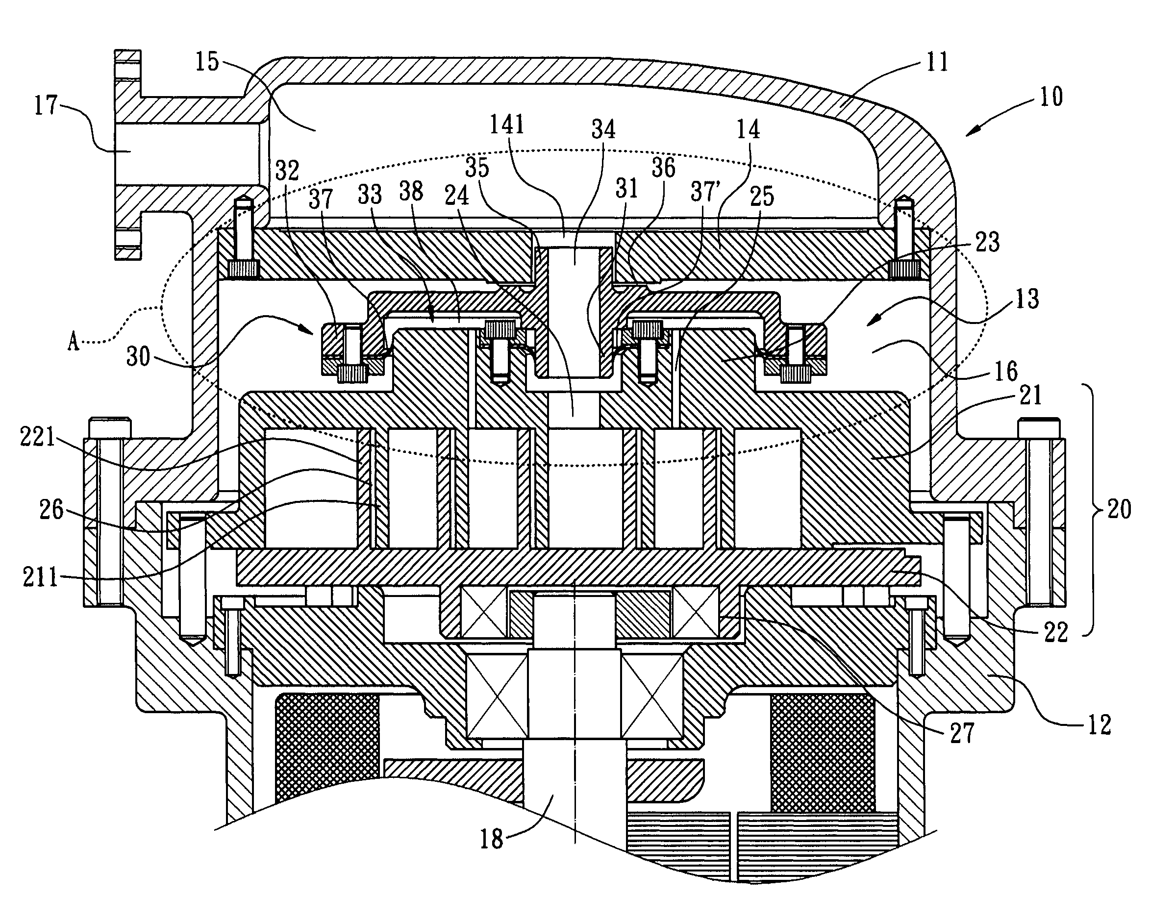
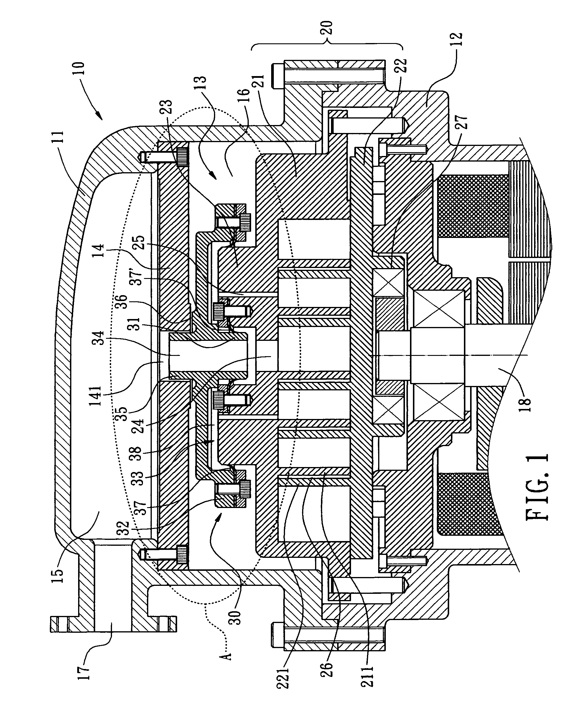
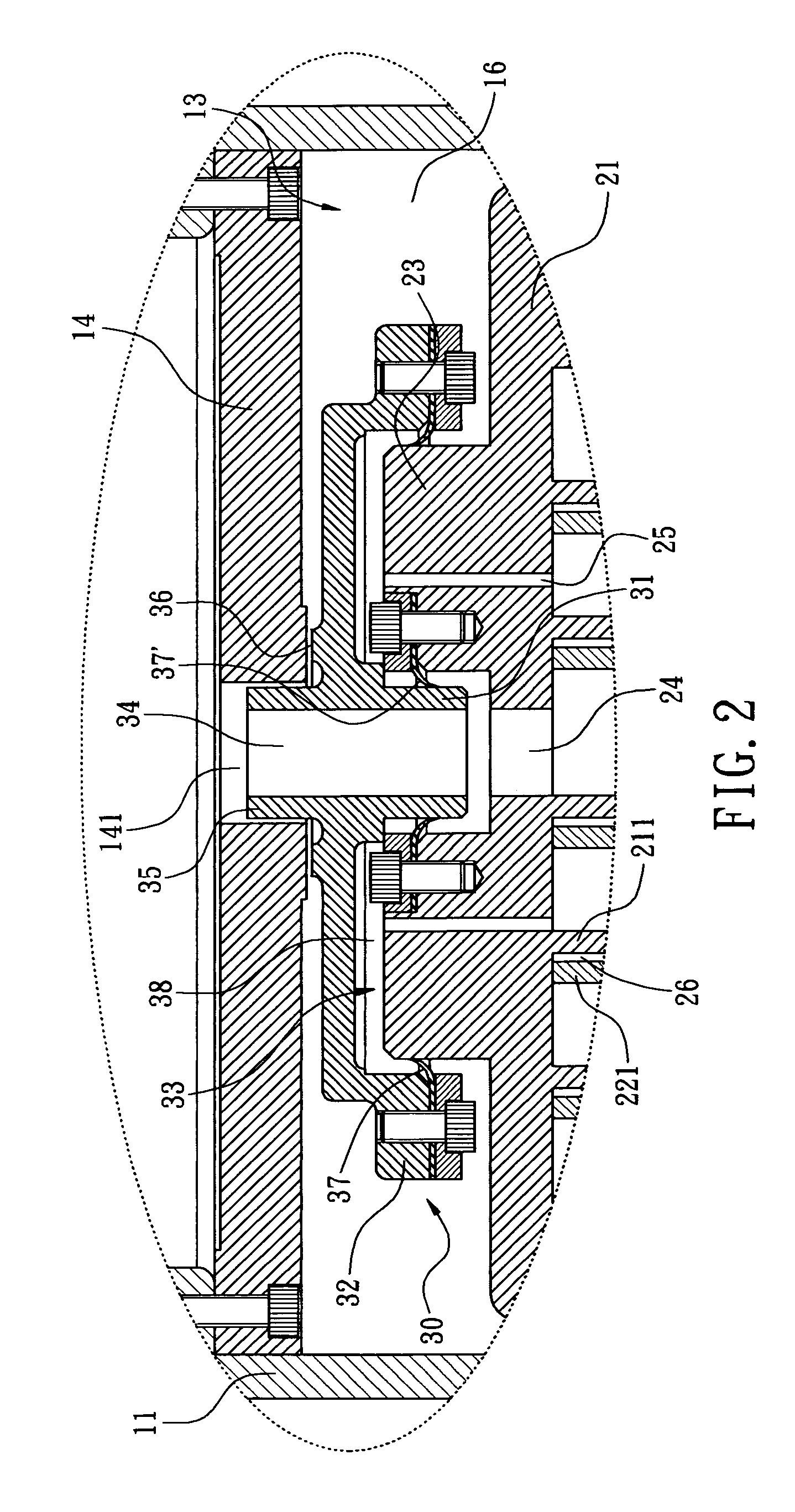
[0017]Referring to FIG. 1 and FIG. 2, an axial sealing structure of a scroll compressor in accordance with the present invention includes a housing 10, a scroll device 20, and a floating seal member 30.

[0018]The housing 10 comprises a first shell 11 and a second shell 12. Both the first shell 11 and the second shell 12 have a hollow cavity formed therein. The first shell 11 is secured to the top of the second shell 12 by means of a plurality of fastening members, or by other methods such as a welding or a soldering process. The hollow cavity of the first shell 11 defines a receiving chamber 13. Inside the receiving chamber 13 a partition 14 is installed to separate the inner space of the housing 10 i...


PUM


Abstract

An axial sealing mechanism of a scroll compressor includes a housing, a scroll device, and a floating seal member with a recess portion and a central channel. The housing includes a first shell and a second shell. The first shell has a receiving chamber. A partition is disposed inside the receiving chamber. The scroll device includes a fixed scroll and an orbiting scroll. A plurality of compression pockets is formed between the fixed scroll and the orbiting scroll. The fixed scroll has a protruding portion with a plurality of orifices. The recess portion of the floating seal member receives the protruding portion of the fixed scroll. Seal elements are respectively secured to the floating seal member and the fixed scroll. An intermediate pressure room is thereby formed between the float seal element and the fixed scroll.

Description

BACKGROUND OF THE INVENTION[0001]The present invention relates in general to an axial sealing structure of a scroll compressor, and more particularly, to an axial sealing structure of a scroll compressor with a floating seal member, capable of both simplifying and reducing the difficulty of the assembling procedure of the scroll compressor. Thereby, a scroll compressor has a better product quality and a lower production cost.[0002]A typical scroll compressor includes a fixed scroll and an orbiting scroll. The orbiting scroll revolves about the fixed scroll. The fixed scroll and the orbiting scroll each has a spiral wrap inter-fitting each other to allow working fluid entering a compression pocket through a suction port. The continuous revolutions of the orbiting scroll compress the working fluid until the working fluid is discharged from an inner discharge port of the fixed scroll. During the compression process the volume of the working fluid is reduced while the pressure thereof i...

Claims


Application Information

Patent Timeline
Patent Type & Authority Patents(United States)
IPC IPC(8): F04C18/00
CPCF04C27/005F04C18/0215
Inventor TARNG, GUANG-DERWANG, MICHAEL
Owner NO 31 1 LANE 169 KANGNING ST
Why Eureka
Try Eureka