Bearing current reduction assembly

a technology of bearings and assemblies, applied in the direction of mechanical energy handling, dynamo-electric machines, supports/encloses/casings, etc., can solve the problems of affecting motor reliability and performance, affecting the reliability of motors, and affecting the effect of motors, so as to reduce or eliminate the current flow from the bearings from the rotor to the stator, reduce or eliminate the effect of current flow through the bearings

Inactive Publication Date: 2006-01-10
GENERAL ELECTRIC CO
View PDF14 Cites 28 Cited by
  • Summary
  • Abstract
  • Description
  • Claims
  • Application Information

AI Technical Summary

Benefits of technology

[0006]The charge concentrator concentrates electrical charge to produce a higher electrical field concentration through the clearance than occurs within a bearing. Accordingly, during operation of an induction motor with an adjustable speed drive, charge build up between the rotor shaft and a stator discharges at the charge concentrator instead of within a bearing. More specifically, rotor to stator currents through the bearings are reduced or eliminated.
[0007]Accordingly, the bearing current reduction assembly provides a low cost bearing assembly that reduces or eliminates current flow through the bearings to improve motor reliability and performance while avoiding costly maintenance issues.

Problems solved by technology

High speed switching of power supplied to these motors often results in charge build up between the rotor and the stator until a sparking voltage develops across the bearing.
After the initial spark, a capacitive coupling between the rotor and stator provide a damaging “follow on” current through the bearing.
This current damages the bearing thus affecting motor reliability and performance.
Insulated bearings, shaft brushes, and modified drive circuits have been employed to reduce and / or eliminate damaging current flow through the bearings, but tend to increase the cost of the motor, reduce motor performance, or introduce costly maintenance issues.

Method used


Image

  • Bearing current reduction assembly
  • Bearing current reduction assembly
  • Bearing current reduction assembly

Examples


Embodiment Construction

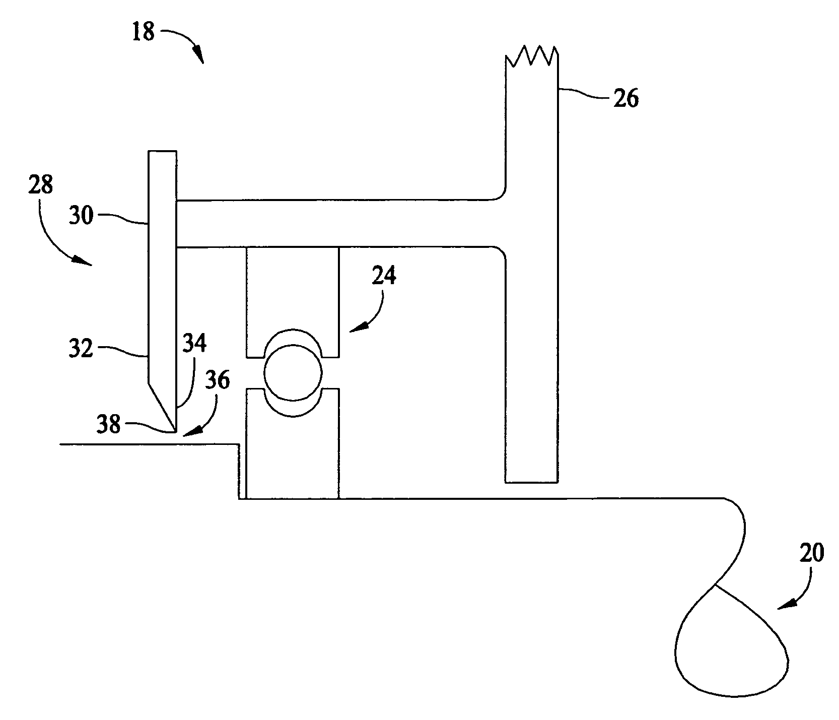
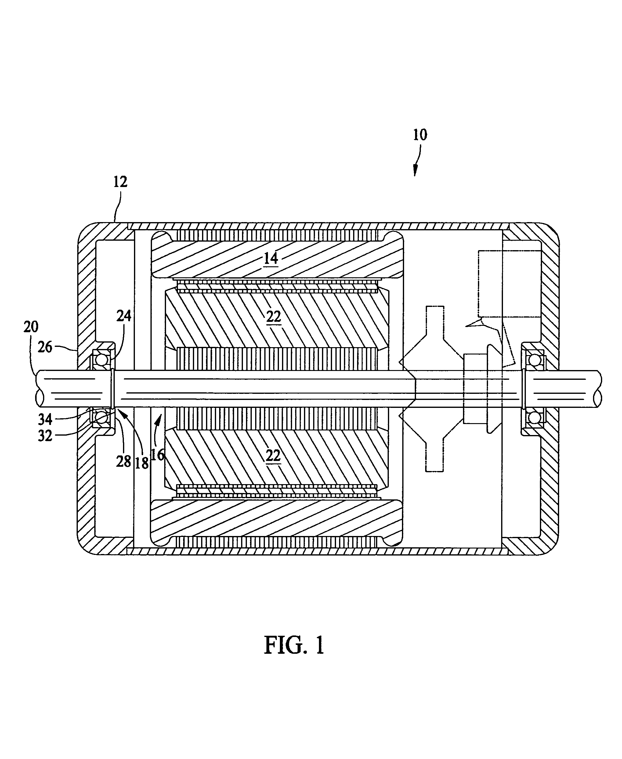
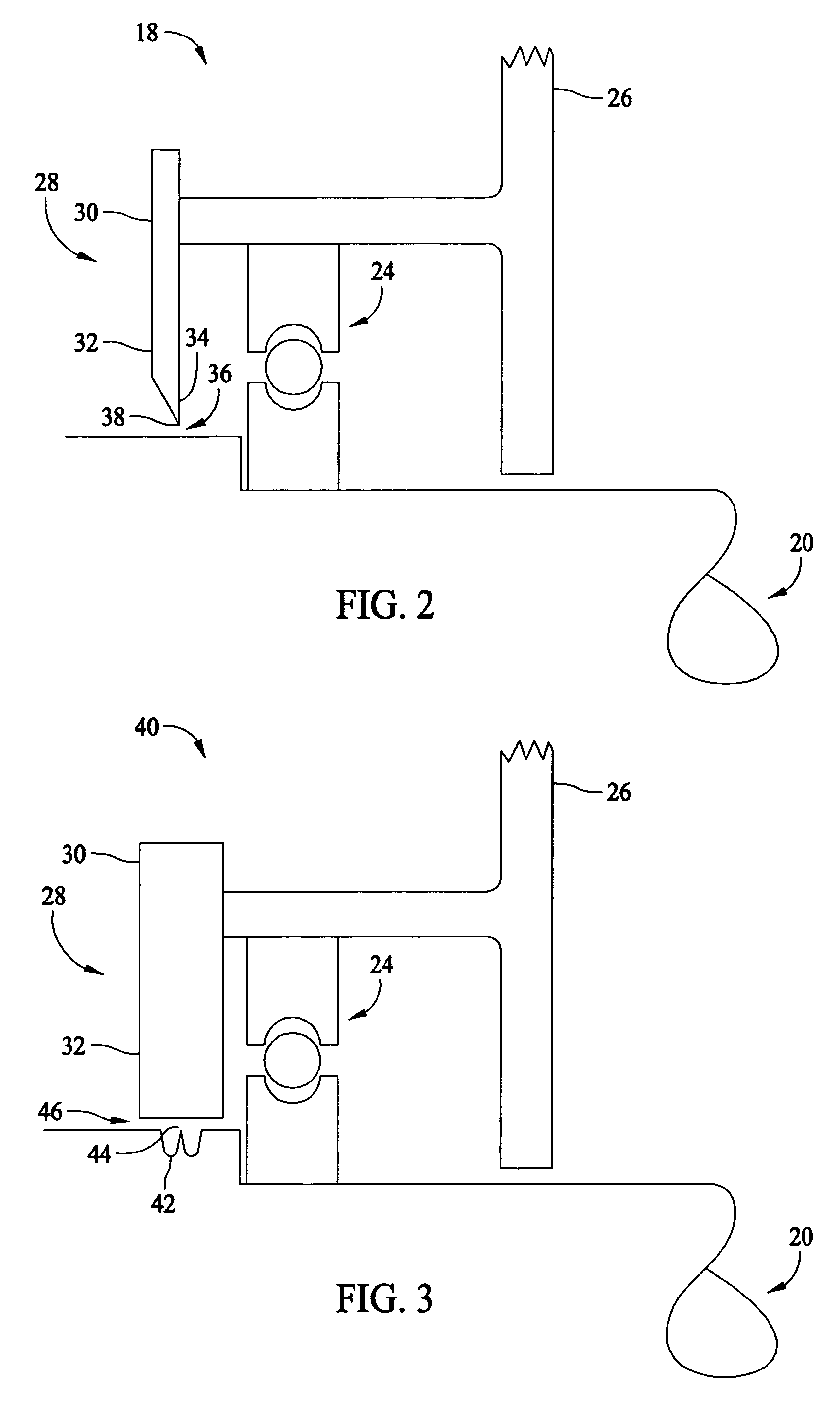
[0011]FIG. 1 is a cross-sectional view of a motor assembly 10 including a motor housing 12, a stator 14 having a plurality of windings, a rotor assembly 16 and a bearing current reduction assembly 18. Rotor assembly 16 includes a rotor shaft 20 mounted on a rotor core 22. A bearing 24 is positioned between an endshield 26 and an inner bearing cap 28.

[0012]Energizing the stator windings with alternating current produces a changing magnetic field or flux within rotor core 22 causing rotor shaft 20 to rotate. The angular velocity of rotor shaft 20 is partially a function of the power delivered to motor assembly 10. Typically, an adjustable speed drive circuit (not shown) is coupled to an inverter (not shown) and motor assembly 10 to vary an angular velocity of rotor shaft 20. High speed switching of power supplied to motor assembly 10 often produces a charge build up between rotor shaft 20 and stator 14.

[0013]Bearing current reduction assembly 18 provides an electrical path from rotor ...


PUM


Abstract

An electric motor with an adjustable speed drive includes a bearing current reduction assembly including a charge concentrator providing a higher electric field concentration through a clearance between an inner bearing cap and a rotor shaft than occurs within a bearing. Accordingly, damaging rotor to ground currents through a bearing are reduced or eliminated. The charge concentrator is disposed on either the rotor shaft or the inner bearing cap, or both.

Description

BACKGROUND OF THE INVENTION[0001]This invention relates generally to electric motors and, more particularly, to bearing assemblies for electric motors with adjustable speed drives.[0002]A / C electric motors typically include a motor housing, a stator including one or more stator windings, and a rotor assembly. The rotor assembly includes a rotor core and a rotor shaft extending through the rotor core. The motor housing includes at least one endshield and houses at least a portion of the rotor assembly. Electric motors also typically include at least one bearing sized to receive and support the rotor shaft, and at least one inner bearing cap separated from the bearing. Typically, the bearing is positioned between an endshield and an inner bearing cap and facilitates rotation of the rotor shaft when the stator windings are energized. An adjustable speed drive circuit is coupled to an inverter and the motor to selectively vary the motor speed as desired in a particular application.[0003...

Claims


Application Information

Patent Timeline
Patent Type & Authority Patents(United States)
IPC IPC(8): H02K11/00H02K5/16
CPCH02K11/0089H02K5/173H02K11/40
Inventor MARTINY, JR., WALTER JOHN
Owner GENERAL ELECTRIC CO
Why Eureka
Try Eureka