Condom testing apparatus

a testing apparatus and chamber technology, applied in the direction of fluid tightness measurement, instruments, structural/machine measurement, etc., can solve problems such as deemed defective, and achieve the effect of increasing the testing rate and reducing the spacing of test mandrels

Inactive Publication Date: 2006-01-10
AGRI DYNAMICS
View PDF5 Cites 12 Cited by
  • Summary
  • Abstract
  • Description
  • Claims
  • Application Information

AI Technical Summary

Benefits of technology

[0011]In order to minimize spacing of the test mandrels for the purpose of increasing the testing rate, at least two sets of condom-contacting electrode members are provided, wherein each individual set of condom-contacting electrode members tests less than the full 360 degree circumference of the condom mounted on the mandrel. Each condom is passed through a testing zone containing the at least two sets of condom-contacting electrode members, and the mandrel is rotated as it passes through the testing zone. In an embodiment wherein there are two sets of condom-contacting electrode members, each set tests between 360 and 180 degrees of the condom circumference, and the sets are spaced along the mandrel travel direction such that sufficient rotation of the mandrel occurs during travel from the first set to the second set to insure that the tested portions of the condom circumference overlap. Because the sets of condom-contacting electrode members are spaced, a second condom loaded mandrel is tested on the first set of condom-contacting electrode members simultaneously with a first condom loaded mandrel being tested on the second set of condom-contacting electrode members, thereby allowing the mandrels to be more closely spaced.

Problems solved by technology

If the electrical circuit containing any one of the condom-contacting electrode members and the conductive mandrel is closed due to the arcing of current through a defect, this state is detected and the condom is deemed defective and is subsequently discarded.

Method used


Image

  • Condom testing apparatus
  • Condom testing apparatus
  • Condom testing apparatus

Examples


Embodiment Construction

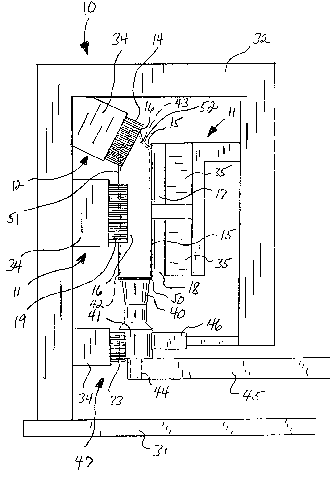
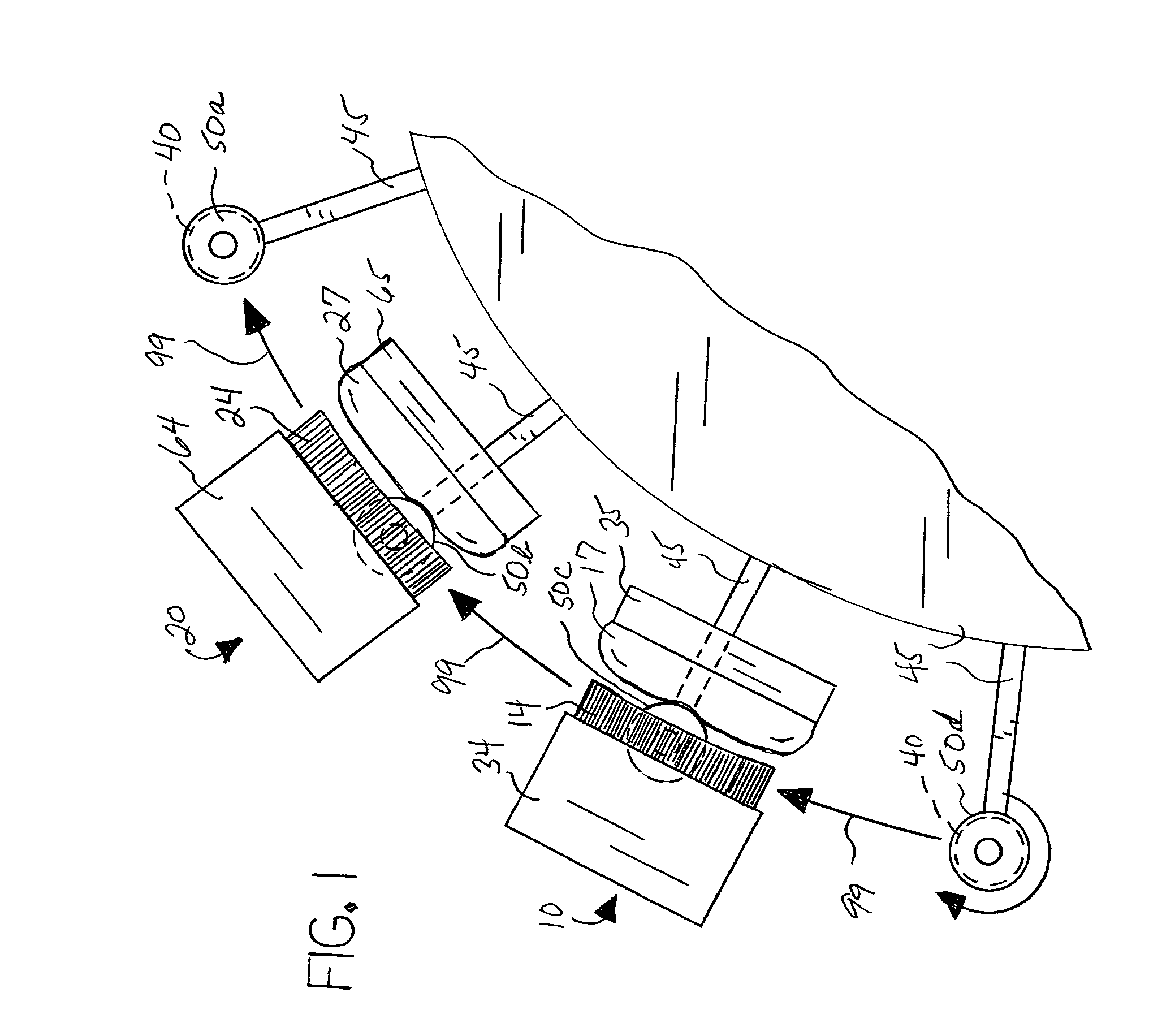
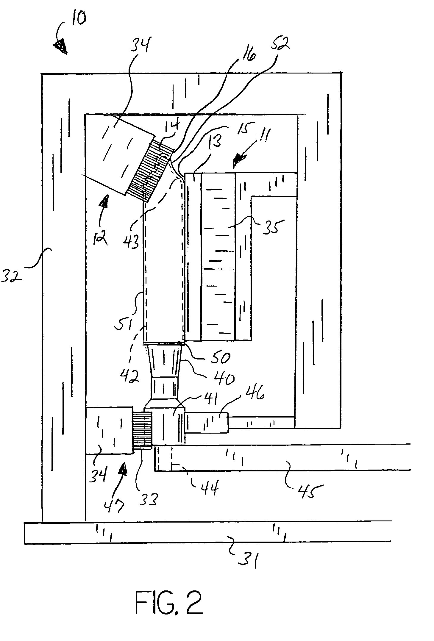
[0018]With reference to the drawings, the invention will now be described in detail with regard for the best mode and the preferred embodiment. For purposes of this disclosure, the invention will be arbitrarily described such that the central axes of the mandrels are oriented vertically with the nipple end of the mandrel and condom on top, and such that the mandrels are positioned on a platform that rotates or moves horizontally, such that any references to relative direction are based on this construct. Furthermore, in this disclosure the individual mandrels are described as rotating clockwise and the platform as rotating clockwise. It is understood, however, that the orientation and rotation directions of the condom defect testing apparatus may be varied without departing from the scope of the claimed invention.

[0019]In general, the invention is a condom defect testing apparatus for testing individual condoms 50 for defects, such as holes, tears or thin-walled regions susceptible ...


PUM

PropertyMeasurementUnit
circumferenceaaaaaaaaaa
distanceaaaaaaaaaa
diameteraaaaaaaaaa

Abstract

A condom testing apparatus having a plurality of electrically conductive mandrels having condoms loaded thereon, a first set of condom-contacting electrode members, a second set of condom-contacting electrode members, and a gapped electrical circuit between each of the mandrels and the first set of condom-contacting electrode members and between each of the mandrels and the second set of condom-contacting electrode members during testing, wherein defects within a condom being tested are detected by passage of current between the mandrels and the first and second sets of condom-contacting electrode members, wherein the first set of condom-contacting electrode members contacts less than 100 percent of the circumference of each of the condoms and the second set of condom-contacting electrode members contacts less than 100 percent of the circumference of each of the condoms, such that two condoms can be tested at once.

Description

BACKGROUND OF THE INVENTION[0001]This invention relates generally to the field of machines, equipment or apparatuses used to test condoms for holes, excessively thin walls or other imperfections prior to packaging and distribution. More particularly, the invention relates to such machines, equipment or apparatuses that utilize electrical current to determine the presence of such imperfections.[0002]Minute holes, tears, or excessively thin wall areas subject to failure during use are unacceptable and render a condom defective. By virtue of their intended use, it is absolutely essential that condoms provide a complete and impermeable barrier. Minute holes undetectable under visual inspection and excessively thin spots in the condom wall likely to fail in use must be discovered. Because the manufacturing process produces huge numbers of condoms at a high rate and because the material of construction, typically a latex or similar plastic, is purposely very thin and elastic, there is alw...

Claims


Application Information

Patent Timeline
Patent Type & Authority Patents(United States)
IPC IPC(8): G01N27/00
CPCG01M3/027G01N27/205G01N27/041G01M3/40G01N27/00G01R31/08
Inventor WHITTEN, JAMES R.
Owner AGRI DYNAMICS
Why Eureka
Try Eureka