

Baffle vibration reducing
a technology of vibration reduction and baffle, which is applied in the direction of transducer diaphragms, electric apparatus casings/cabinets/drawers, instruments, etc., can solve the problems of excessive vibration of the structure, insufficient stiffness of the structure to resist vibration, and light damped, so as to reduce the resultant force applied, reduce unwanted mechanical vibration of the supporting structure, and enhance acoustic output
- Summary
- Abstract
- Description
- Claims
- Application Information
AI Technical Summary
Benefits of technology
Problems solved by technology
Method used
Image

Examples
Embodiment Construction
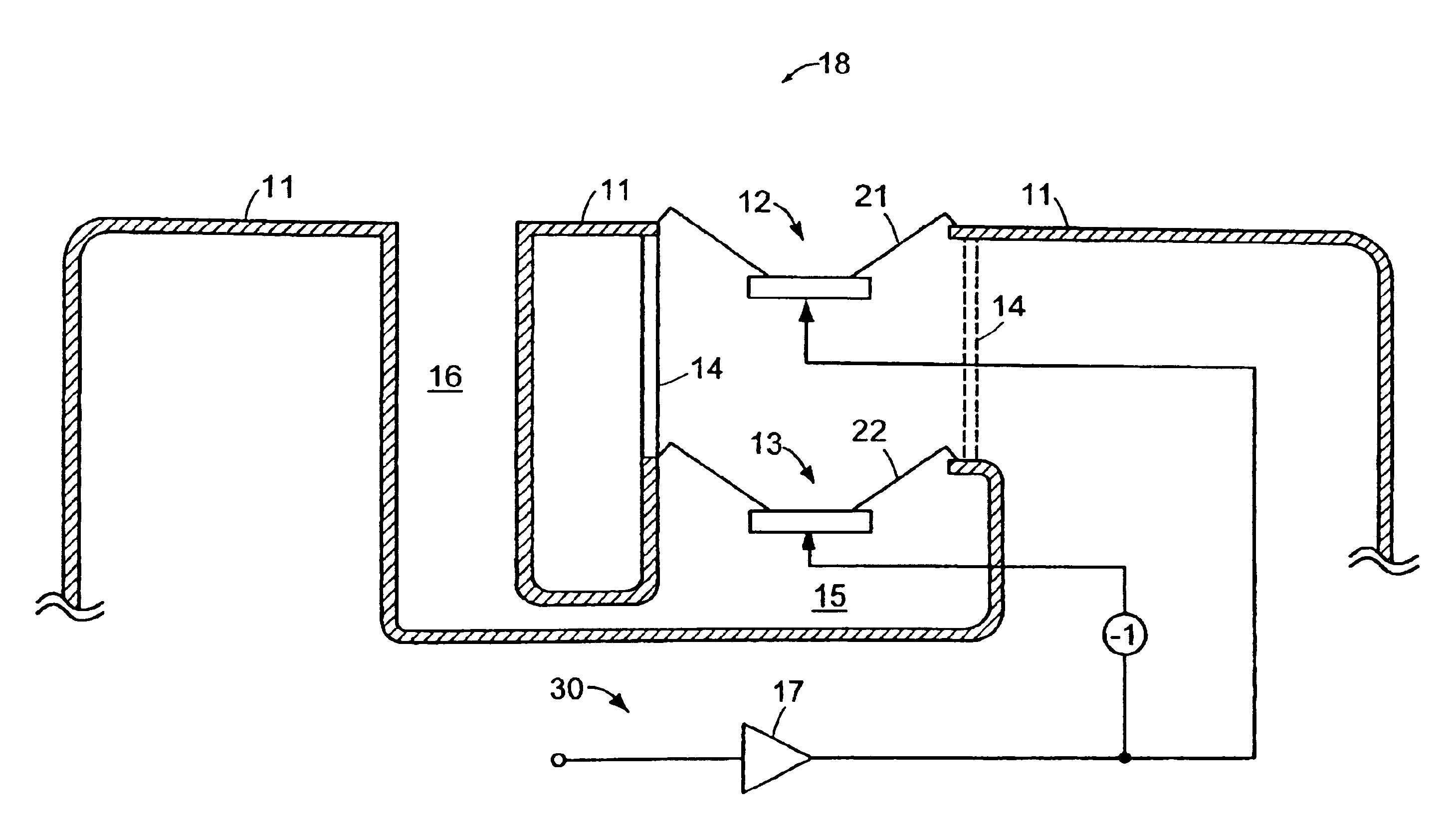
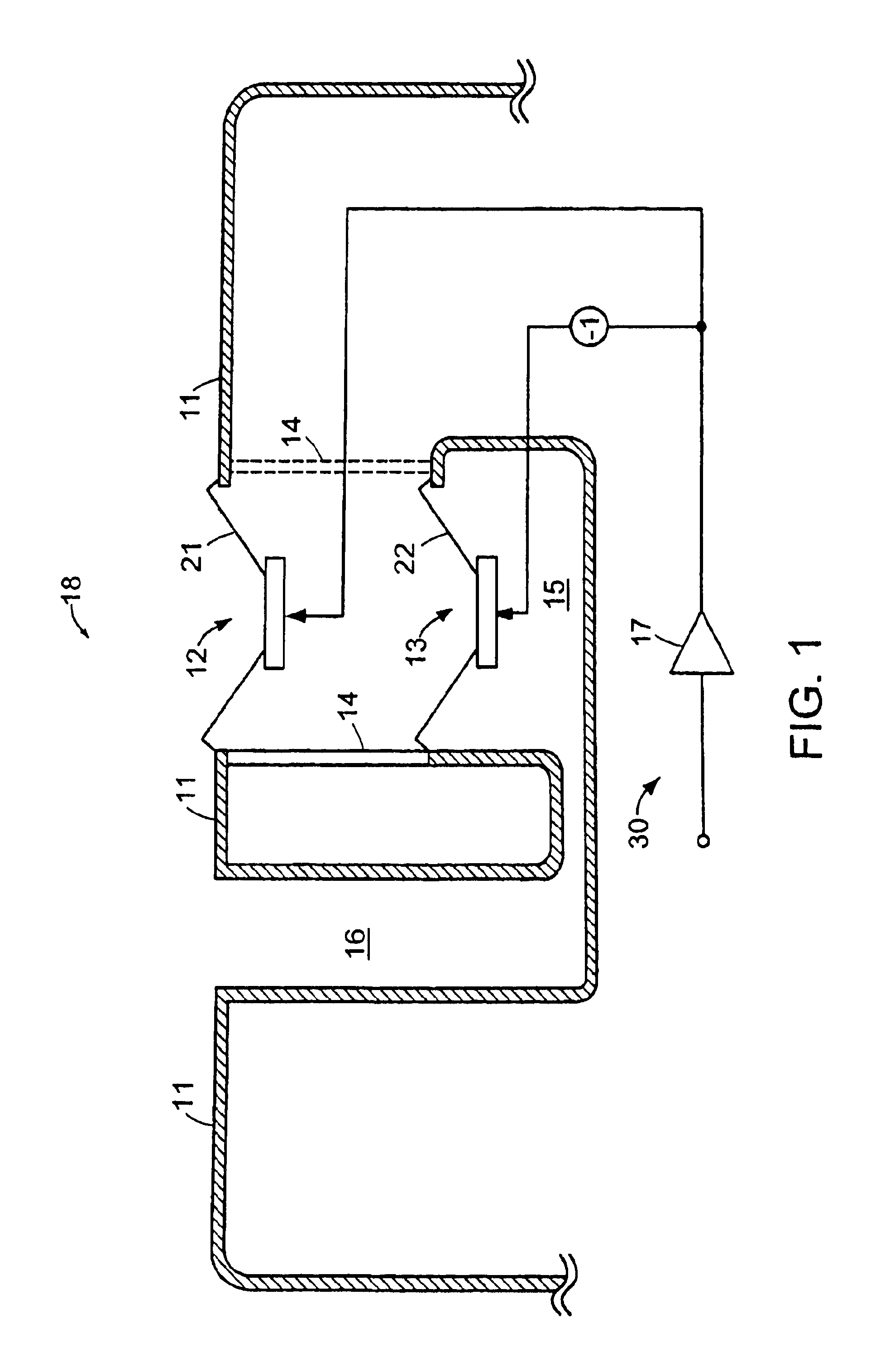
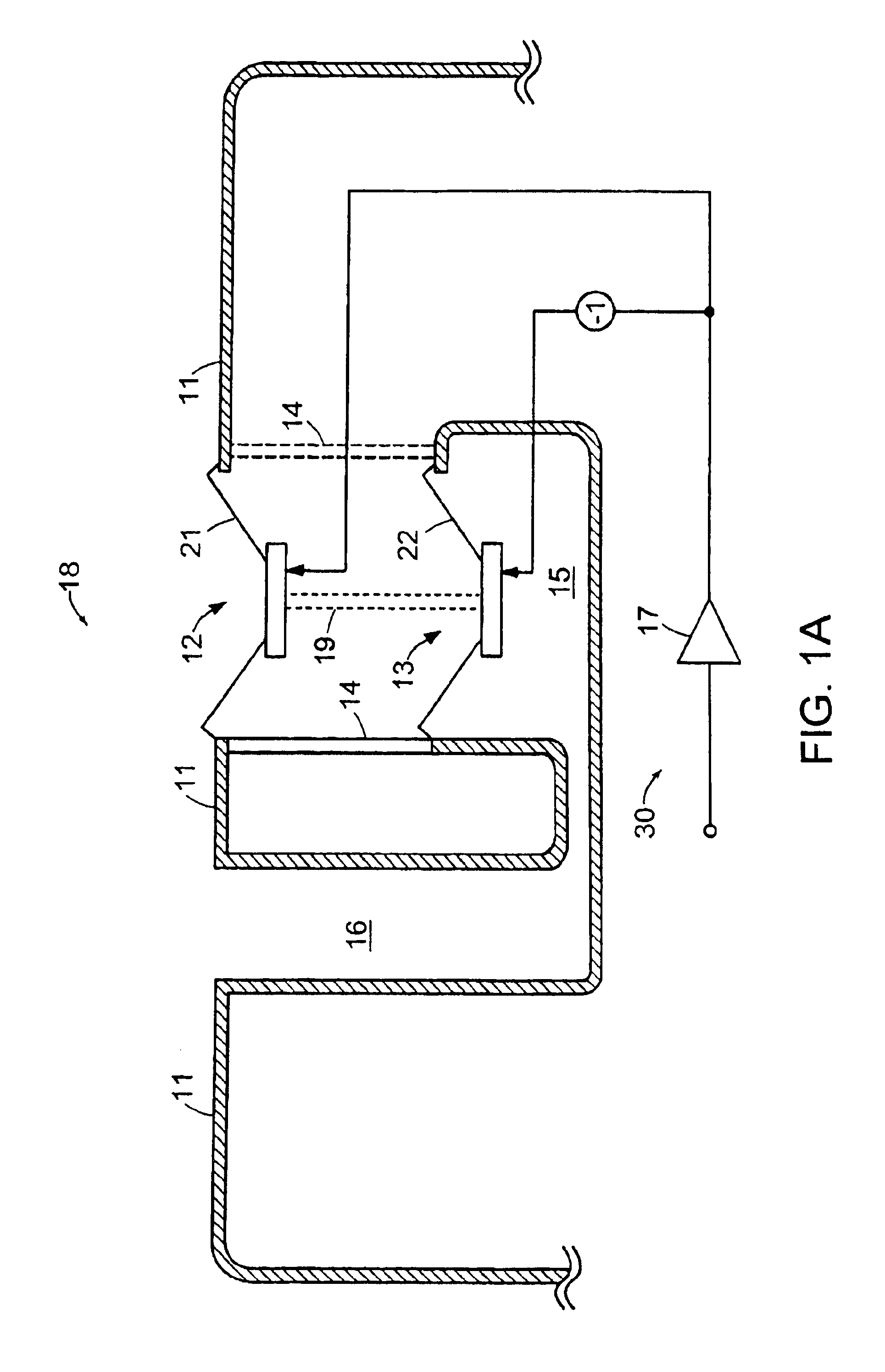
[0010]With reference now to the drawing and more particularly FIG. 1 thereof, there is shown a diagrammatic representation of an embodiment of the invention with structure carried by infinite baffle 11, typically a vehicle rear shelf or door panel carrying a first transducer, such as loudspeaker driver 12, mechanically connected to a second transducer, such as loudspeaker driver 13, preferably identical to loudspeaker driver 12, through mechanical link 14. The two transducers are ideally mounted in substantially parallel planes such that the diaphragms move in the same axial direction. The front side of transducer 12 is directly coupled to listening area 18. If baffle 11 is the rear package shelf of a vehicle, listening area 18 will be the passenger compartment of the vehicle. The second side of transducer 12 is coupled to volume 30, which would be the vehicle trunk if baffle 11 is the rear package shelf. The second side of diaphragm 22 of driver 13 is coupled to the listening area ...
PUM
 Abstract
Description
Claims
Application Information