Discharging four-roller mechanism for diamond wire multi-wire cutting machine
A multi-wire cutting machine and diamond wire technology, which is applied to fine working devices, manufacturing tools, stone processing equipment, etc. problems such as the service life of the electric roller, to achieve the effects of good discharge effect consistency, increase in the number of sheets, and stable and reliable charging effect.
- Summary
- Abstract
- Description
- Claims
- Application Information
AI Technical Summary
Problems solved by technology
Method used
Image
Examples
Embodiment 1
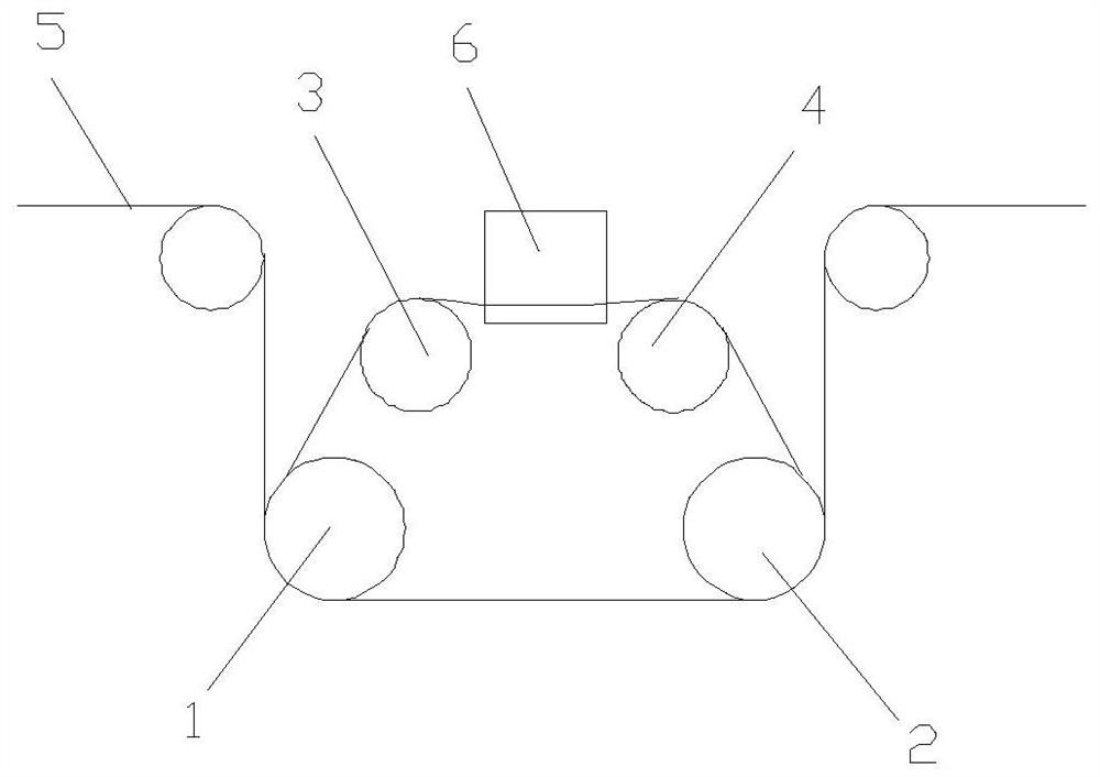
[0031] Such as figure 1 As shown, a discharge four-roll mechanism for a diamond wire multi-wire cutting machine includes a driving roller assembly, a conductive roller assembly, and a conductive element. The diamond wire is wound back and forth between the driving roller assembly and the conductive roller assembly to form a wire network. Since the drive roller assembly and the conductive roller assembly are arranged at intervals along the vertical direction, the upper and lower distances of the wire net are increased, the cutting space is increased, workpieces with larger diameters can be cut, and the processing range is expanded.
[0032] The driving roller assembly includes a first driving roller 1 and a second driving roller 2, and the first driving roller 1 and the second driving roller 2 are arranged in parallel at intervals and have the same structure. The conductive roller assembly includes a first conductive roller 3 and a second conductive roller 4, and the first cond...
Embodiment 2
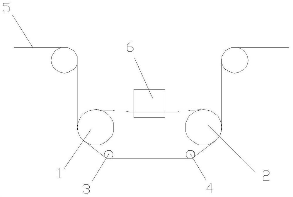
[0037] Such as Figure 1-Figure 3 As shown, the conductive element is in rolling contact with the conductive roller assembly to supply power to the conductive roller assembly, and the first conductive roller 3 and the second conductive roller 4 are provided with conductive elements, and the conductive elements can use conductive slip rings 8 and The conductive wheel 7 mechanism is used to supply power to the first conductive roller 3 and the second conductive roller 4 . Since the first conductive roller 3 and the second conductive roller 4 have the same structure, the specific structure will be described by taking the first conductive roller 3 as an example.
[0038] The surface of the first conductive roller 3 is provided with a conductive layer, and the diamond wire 5 is in rolling contact with the conductive layer, which reduces the friction between the conductive roller assembly and the diamond wire 5, slows down the wear speed, and is conducive to ensuring the power-in ef...
Embodiment 3
[0041] Such as figure 1 , figure 2 As shown, the first driving roller 1 is provided with a first wire groove perpendicular to its axis, and the second driving roller 2 is provided with a second wire groove perpendicular to its axis and corresponding to the first wire groove. The first conductive roller 3 is provided with a first transition slot perpendicular to its axis, and the second conductive roller 4 is provided with a second transition slot perpendicular to its axis and corresponding to the first transition slot. At the same time, a plurality of the first wire groove, the second wire groove, the first transition wire groove and the second transition wire groove are parallel and equally spaced, and the diamond wire 5 is arranged along the first wire groove, the second wire groove, the second wire groove The first transition slot and the second transition slot are routed to meet the wire mesh requirements of the multi-wire cutting machine.
[0042] Specifically, the wir...
PUM
 Abstract
Description
Claims
Application Information
 - R&D
- Intellectual Property
- Life Sciences
- Materials
- Tech Scout
- Unparalleled Data Quality
- Higher Quality Content
- 60% Fewer Hallucinations
Browse by: Latest US Patents, China's latest patents, Technical Efficacy Thesaurus, Application Domain, Technology Topic, Popular Technical Reports.
© 2025 PatSnap. All rights reserved.Legal|Privacy policy|Modern Slavery Act Transparency Statement|Sitemap|About US| Contact US: help@patsnap.com


