Hydrostatic transmission

Inactive Publication Date: 2006-01-17
HYDR0 GEAR
View PDF41 Cites 33 Cited by
  • Summary
  • Abstract
  • Description
  • Claims
  • Application Information

AI Technical Summary

Benefits of technology

[0014]A further object of this invention is to provide an improved and novel design of a center section for an HST, whereby the output shaft of the hydrostatic motor is secured at least partially by the center section and is positioned so that the axis of the output shaft is located below the plane of the surface on which the hydrostatic pump is mounted on the center section. The benefits of this arrangement include, among other things, a reduced height of the pump, motor and center section, which can reduce the overall height of the unit and/or provide more flexibility for mounting other HST elements. The horizontal mounting of the center section also allows for the use of the vertical split line as disclosed herein and the unique arrangement of the HST elements within the housing units.
[0015]A further object of this invention is to provide an improved and novel expansion chamber that can be bolted or otherwise secured to the HST and which prevents leakage or spillage of the hydraulic fluid therefrom. In a preferred embodiment this chamber is external to the housing and includes an internal tube extending from the top of the tank to the bottom, although variations on this design will be obvious to one of skill in the art. The use of an external tank allows for use of a smaller transmission housing, and reduces the possibilities of leakage due to gear splash and oil movement at various operating angles. The internal tube provides siphoning action which allows for, among other things, greater flexibility in the location of the tank.
[0016]A further feature disclosed herein in one embodiment is an improved design of a friction pack which enables the vehicle user to maintain the position of the pump swash plate, and thus the speed and direction of the vehicle. Friction packs have been known for years in connection with HSTs and have been shown in, for example, U.S. Pat. No. 5, 201,692. The improved design sho

Problems solved by technology

Using a traditional transaxle design, it is very difficult to achieve rear discharge, as the input s

Method used


Image

  • Hydrostatic transmission
  • Hydrostatic transmission
  • Hydrostatic transmission

Examples


Embodiment Construction

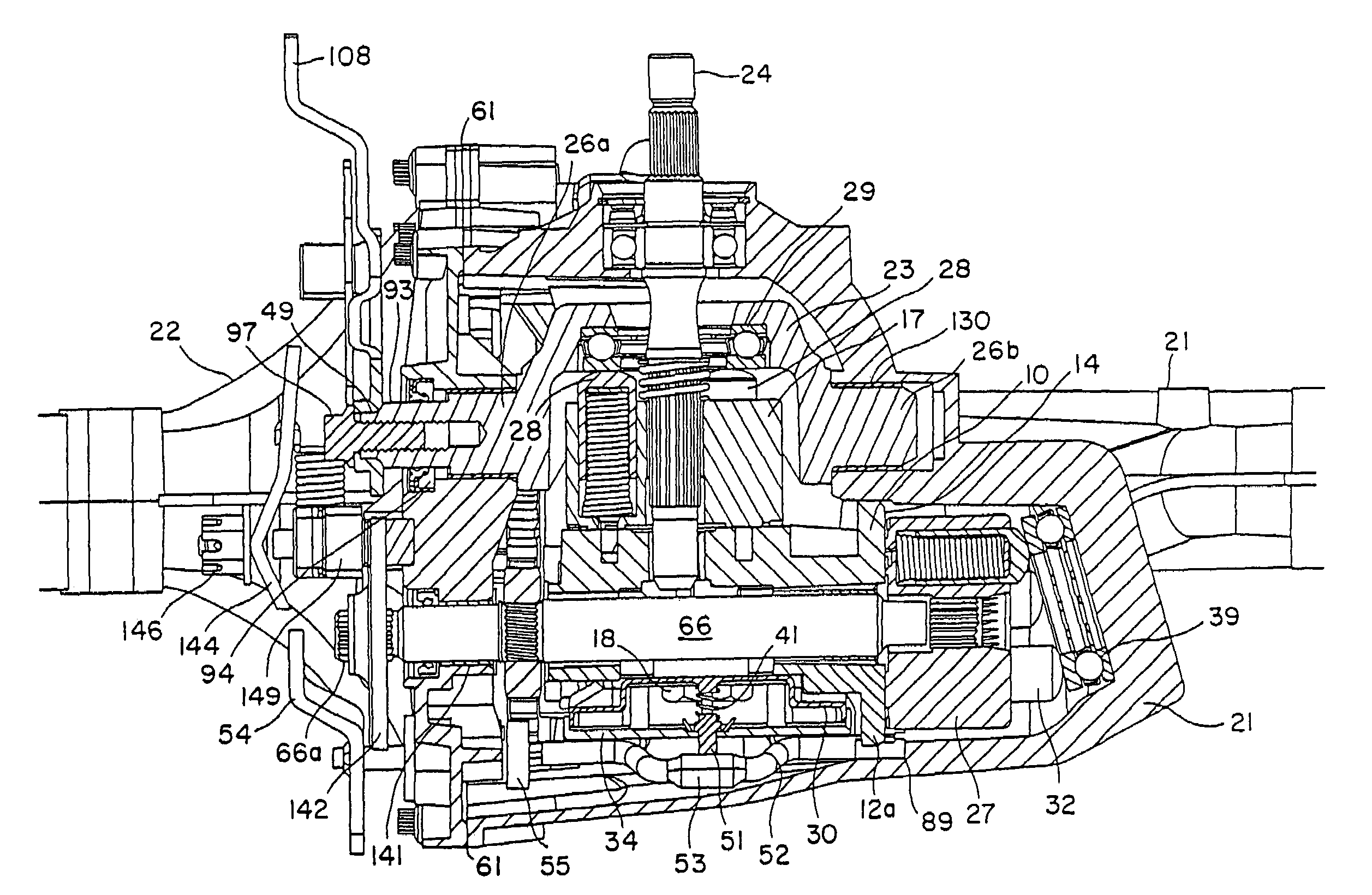
[0062]The present invention is discussed in relation to transmissions, and in particular, hydrostatic transmissions; other uses will be apparent from the teachings disclosed herein. The present invention will be best understood from the following detailed description of exemplary embodiments with reference to the attached drawings, wherein like reference numerals and characters refer to like parts, and by reference to the following claims.

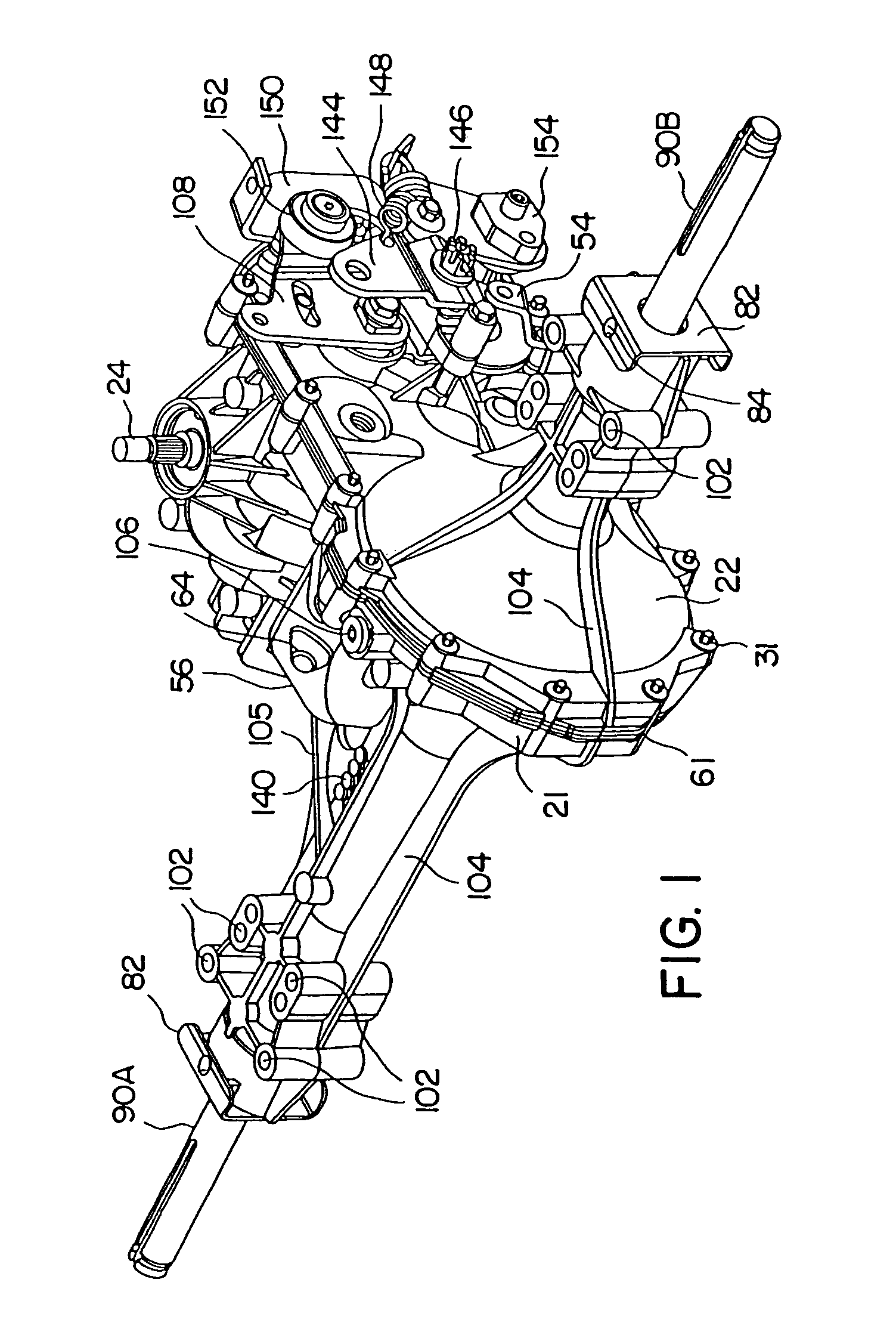
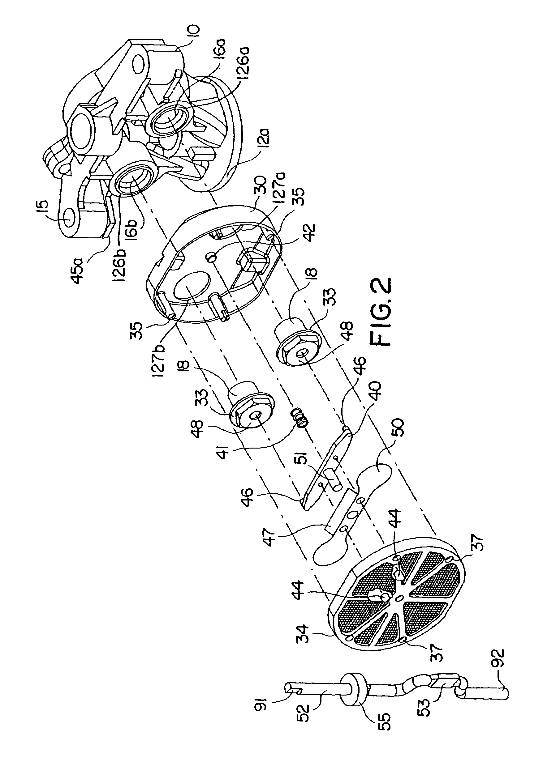
[0063]The figures herein, and in particular, FIGS. 1, 3, 5, 6 and 9 illustrate an IHT configured with a vertically split housing with main casing 21 and side casing 22. The arrangement of these housing elements are a key feature of the design, but certain embodiments of this invention do not require any specific housing configuration, and other housing configurations can be accommodated therewith. All specifics of an IHT are not shown in these figures, as the general operation of an IHT is known in the art. In general, where different embodiments o...


PUM


Abstract

An axle driving apparatus having a housing having two members joined along a joint surface and a hydraulic axial piston pump and motor mounted on a center section located in the housing, wherein the pump and motor are mounted perpendicular to one another. The motor is engaged to a fixed thrust bearing located in the housing and the center section is located entirely between the joint surface and the thrust bearing.

Description

[0001]This application is a continuation of U.S. application Ser. No. 10 / 376,889 filed on Feb.28, 2003, now U.S Pat. No. 6,688,433; which is a continuation of U.S. application Ser. No. 10 / 271,484 filed Oct. 16, 2002 and now U.S Pat. No. 6,637,293; which is a continuation of U.S. application Ser. No. 09 / 845,989 filed Apr. 30, 2001 and now U.S. Pat. No. 6,487,935; which is a continuation of U.S. application Ser. No. 09 / 354,963, filed Jul. 16, 1999, and now U.S. Pat. No. 6,253,637; which is a continuation-in-part of U.S. application Ser. No. 09 / 196,182, filed on Nov. 20, 1998, and now U.S. Pat. No. 6,122,996. U.S. application Ser. No. 09 / 845,989 is also a continuation of U.S. application Ser. No. 09 / 773,994, filed Feb. 1, 2001 and now U.S. Pat. No. 6,318,080; which is a continuation of U.S. application Ser. No. 09 / 196,183 filed on Nov. 20, 1998, and now U.S. Pat. No. 6,185,936. These prior applications are incorporated herein in their entirety by reference.BACKGROUND OF THE INVENTION[0...

Claims


Application Information

Patent Timeline
IPC IPC(8): F16D39/00
CPCB60K17/105Y10T74/2186
Inventor HAUSER, RAYMONDSCHREIER, JOHN
Owner HYDR0 GEAR
Why Eureka
Try Eureka