Dynamic lordotic guard with movable extensions for creating an implantation space posteriorly in the lumbar spine

a lumbar spine and lordotic guard technology, applied in the field of dynamic lordotic guard with movable extensions for creating an implantation space posteriorly in the lumbar spine, can solve the problems of robbery of the structure portion of the vertebrae, difficult to remove a distractor element, etc., and achieves the effect of convenient insertion and removal, quick, safe, effective and accurate spacing apart and positioning

Inactive Publication Date: 2006-01-17
WARSAW ORTHOPEDIC INC
View PDF14 Cites 166 Cited by
  • Summary
  • Abstract
  • Description
  • Claims
  • Application Information

AI Technical Summary

Benefits of technology

[0030]The present invention has a number of embodiments, at least some of which have as an object of at least one embodiment of the present invention to provide a device and method for quickly, safely, effectively, and accurately spacing apart and positioning a pair of adjacent vertebral bodies to receive an implant, which is anything designed to be left in the body for an extended length of time, working upon the properly positioned vertebral body end plate regions adjacent a disc space so as to, while preserving that end plate region at least in part, remove bone to produce a receiving surface corresponding to an implant having upper and lower surfaces to be implanted between the adjacent vertebrae.
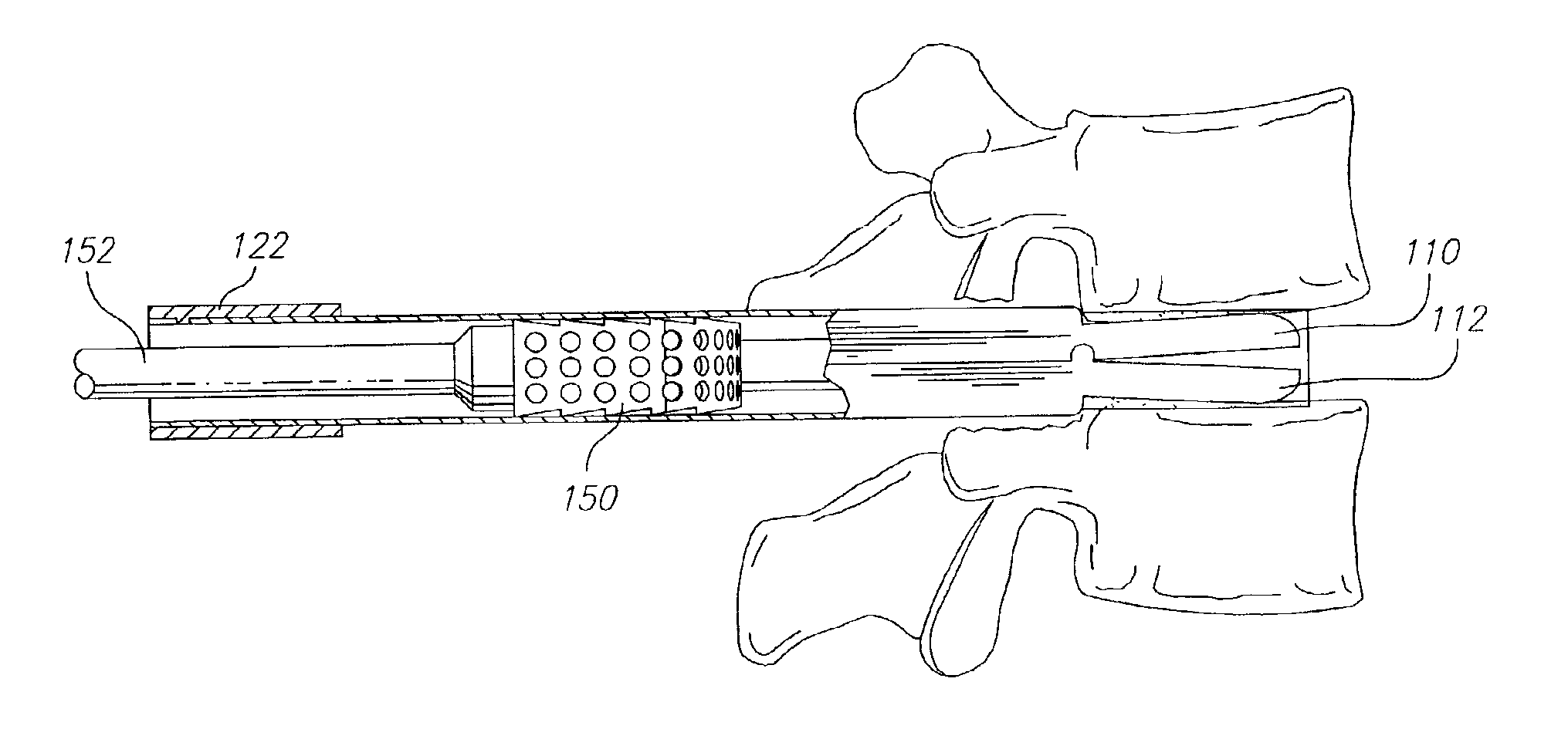
[0031]It is a further object of at least one embodiment of the present invention to provide a device and method that permits the insertion of disc penetrating extensions of a guard into the disc space posteriorly in a first position that facilitates insertion and removal of the disc penetrating extensions into and from the disc space and then permits the disc penetrating extensions to be moved into a second position that orients the adjacent vertebral bodies in a preferred lordotic relationship relative to the device and each other.

Problems solved by technology

Then, after an implant is inserted, it may be difficult to remove a distractor element such as a guard having disc penetrating extensions having a maximum height greater then the height of the disc space posterior height.
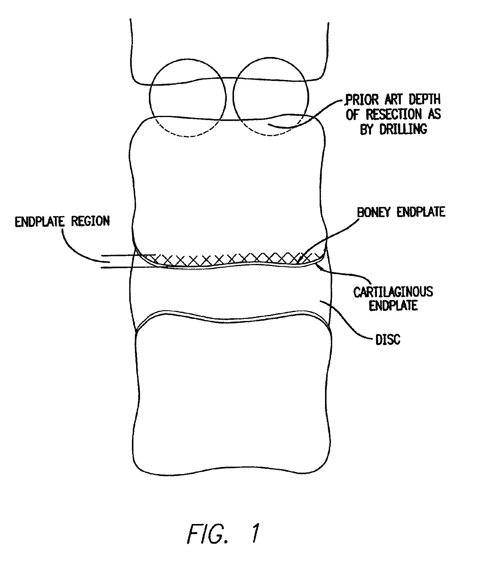
Such a surgical procedure necessarily results in the loss of the hardest and strongest bone tissue of the vertebrae—the end plate region—and thereby robs the vertebrae of that portion of its structure best suited to absorbing and supporting the loads placed on the spine by everyday activity.

Method used


Image

  • Dynamic lordotic guard with movable extensions for creating an implantation space posteriorly in the lumbar spine
  • Dynamic lordotic guard with movable extensions for creating an implantation space posteriorly in the lumbar spine
  • Dynamic lordotic guard with movable extensions for creating an implantation space posteriorly in the lumbar spine

Examples


Embodiment Construction

[0069]Reference is now made in detail to the present preferred embodiments of the invention, as illustrated in the accompanying drawings.

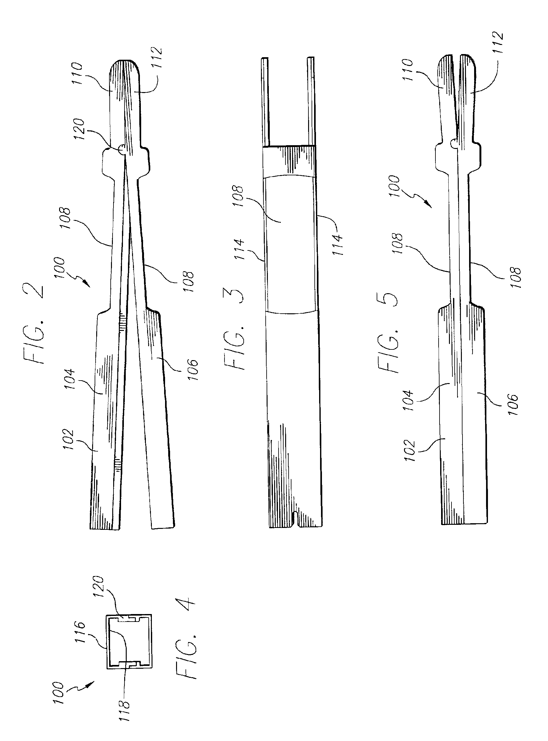
[0070]FIGS. 2-5 are generally directed to an embodiment of a guard having a rectangular cross-section for use in spinal surgery for forming an implantation space between adjacent vertebral bodies of the lumbar spine from a posterior approach. As shown in FIG. 2, a guard 100 has a body 102 with a first portion 104 and a second portion 106. Guard 100 also has disc penetrating extensions 110, 112. In particular, first disc penetrating extension 110 extends from first portion 104 of body 102 and second disc penetrating extension 112 extends from second portion 106 of body 102.

[0071]In preferred embodiments, but not requisite, various windows 108 in guard body 102 allow the surgeon to remove portions of a facet, pedicle, or spinous process in the same procedure as the bone removal of the vertebral bodies for creating an insertion space therebetween. It ...


PUM


Abstract

A lordotic guard and method for guiding a bone removal device to form an implantation space in the human spine and, if desired, for inserting a spinal implant into the implantation space.

Description

[0001]This application is a continuation-in-part of U.S. utility application Ser. No. 10 / 061,236, Feb. 4, 2002, and claims benefit of U.S. provisional application No. 60 / 272,381, filed Mar. 1, 2001, the disclosures of which are incorporated herein by reference.FIELD OF THE INVENTION[0002]The present invention relates to a device for implantation into a disc space between adjacent vertebral bodies in the human spine, and a device and method for working on those portions of the vertebral bodies adjacent that disc space to remove bone material and thereby access vascular bone, and preferably a device and method for protecting the neurological structures such as nerve roots and dural sac proximate the implantation site while providing protected access to form an implantation space and then access the implantation space formed between the adjacent vertebral bodies for insertion of an implant therein. The device and associated method are used to position (space apart and align) the verteb...

Claims


Application Information

Patent Timeline
Patent Type & Authority Patents(United States)
IPC IPC(8): A61B17/56A61B17/02A61B17/16A61B17/17A61F2/00A61F2/30A61F2/44A61F2/46
CPCA61B17/1671A61F2/4611A61B17/1757A61F2230/0069A61B2017/0256A61F2/442A61F2/4455A61F2/4601A61F2002/30143A61F2002/30187A61F2002/30224A61F2002/30235A61F2002/30428A61F2002/30487A61F2002/30574A61F2002/30579A61F2002/30777A61F2002/30785A61F2002/30787A61F2002/30975A61F2002/4475A61F2002/4622A61F2002/4623A61F2002/4627A61F2002/4642A61F2220/0025A61F2230/0017A61F2230/0034A61F2/4603A61F2/4637A61F2002/30593
Inventor MICHELSON, GARY K.
Owner WARSAW ORTHOPEDIC INC
Why Eureka
Try Eureka