Intervertebral allograft spacer
- Summary
- Abstract
- Description
- Claims
- Application Information
AI Technical Summary
Benefits of technology
Problems solved by technology
Method used
Image
Examples
first embodiment
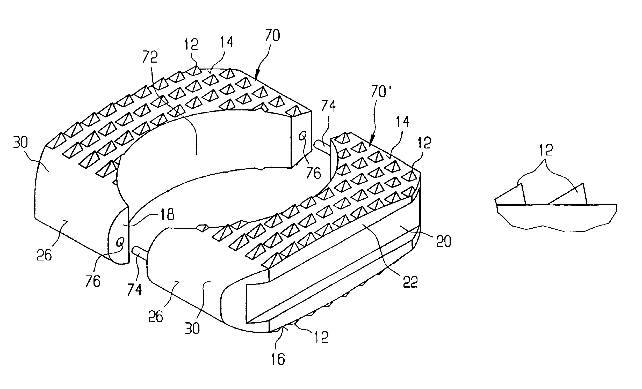
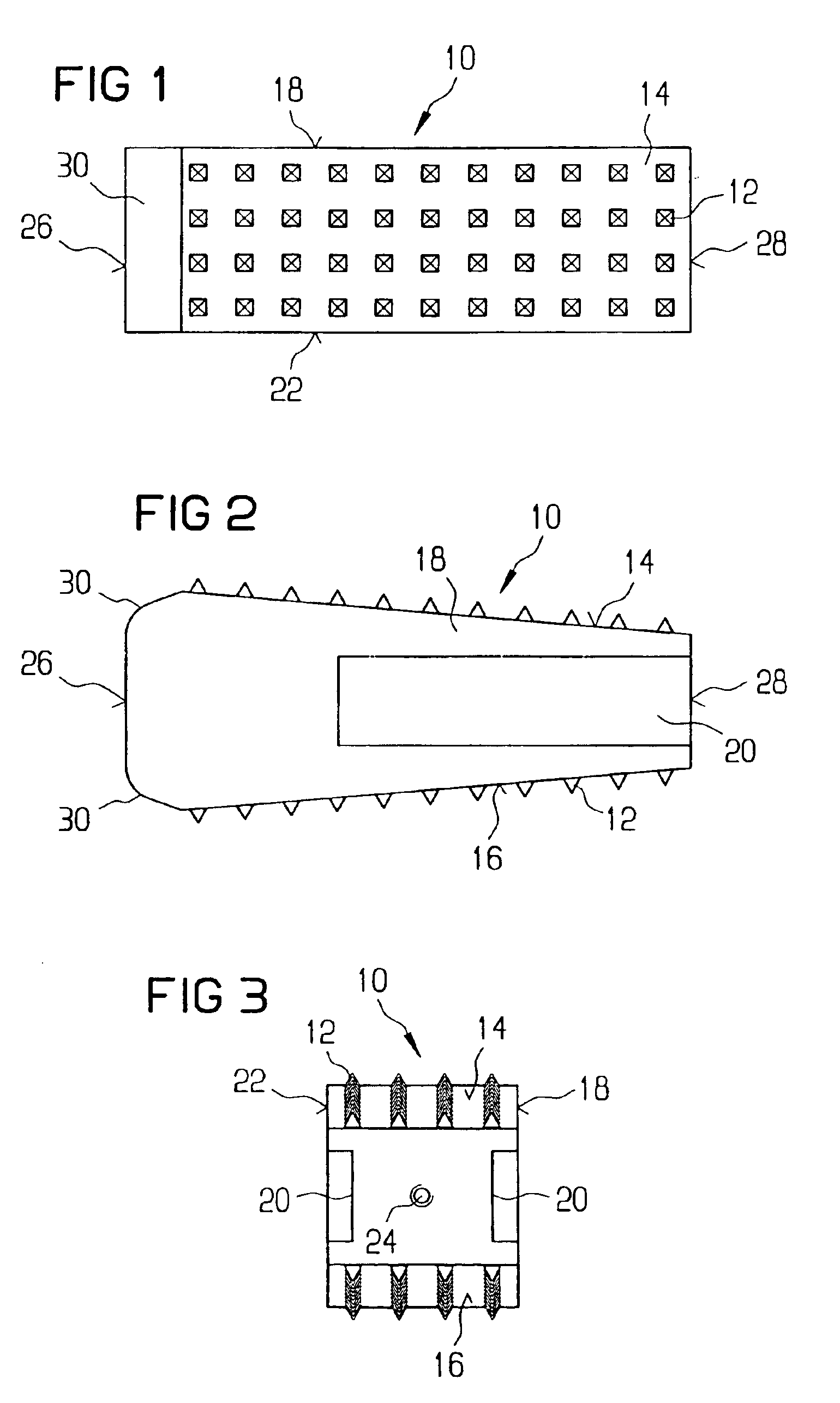
[0031]FIG. 1 shows a top view of intervertebral allograft spacer or implant 10 according to the present invention. Implant 10 conforms in size and shape with a portion of end plates of the vertebrae between which implant 10 is to be implanted. Because implant 10 is an allograft, implant 10 promotes the formation of new bone to fuse the two vertebral bodies together. Although implant 10 will probably be predominantly used in the lumbar region of the spine, implant 10 can be configured for implantation in any region of the spine. Implant 10 has a plurality of teeth 12 on superior and inferior surfaces 14, 16 which provide a mechanical interlock between implant 10 and the end plates. Teeth 12 provide the mechanical interlock by penetrating the end plates. The initial mechanical stability afforded by teeth 12 minimizes the risk of post-operative expulsion of implant 10. Teeth 12 can be pyramid-shaped (FIG. 10A). Preferably, the angle formed from the tip to the base is approximately 60°....
second embodiment
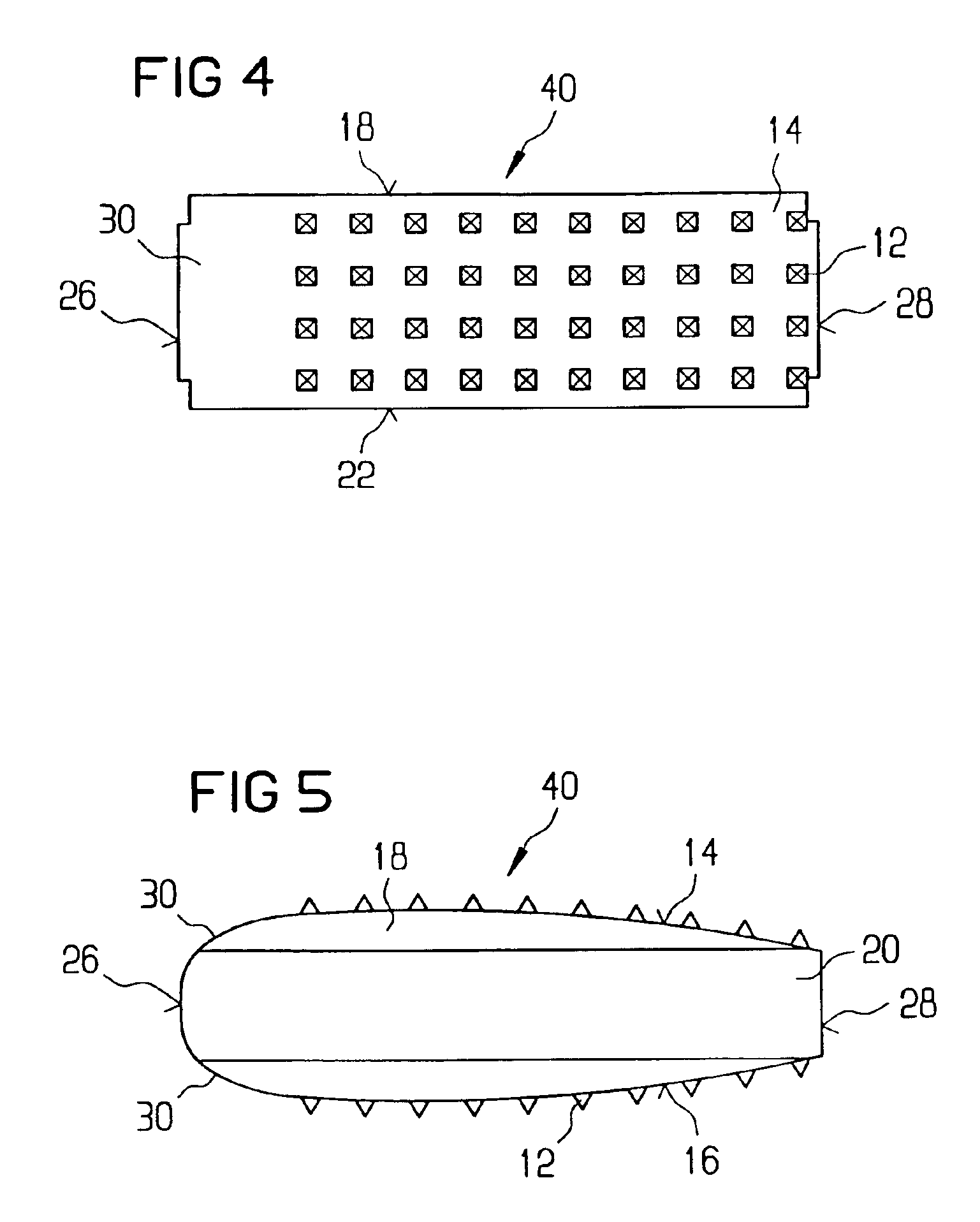
[0037]FIG. 4 shows a top view of an implant 40 according to the present invention. In general, most of the structure of implant 40 is like or comparable to the structure of implant 10. Accordingly, discussion of the like components is not believed necessary. The superior and inferior surfaces 14, 16 of implant 10 are flat planar surfaces. As seen best in FIG. 5, superior and inferior surfaces 14, 16 of implant 40 are curved surfaces which still retain the wedge-shaped profile. The curved surfaces of superior and inferior surfaces 14, 16 of implant 40 are a mirror-image of the topography of the vertebral end plates. Thus, the curved surfaces conform to the contours of the end plates.
third embodiment
[0038]FIG. 6 shows a top view of an implant 50 according to the present invention. In general, most of the structure of implant 50 is like or comparable to the structure of implants 10, 40. Accordingly, discussion of the like components is not believed necessary. As best seen in FIG. 7, implant 50 comprises a top portion 52 joined to a bottom portion 54. As it may be difficult to obtain a single section of allogenic bone from which implant 50 is to be made, fabricating implant 50 in two pieces, i.e. top and bottom portions 52, 54, allows smaller sections of allogenic bone to be used. A top connecting surface 56 and a bottom connecting surface 58 define the interface between top and bottom portions 52, 54. As shown in FIGS. 8A and 8B, top and bottom surfaces 56, 58 have ridges 60 that mate with grooves 62 to interlock top and bottom portions 52, 54. Preferably, ridges 60 and grooves 62 are formed by milling top and bottom surfaces 56, 58 in a first direction and then milling a second...
PUM
| Property | Measurement | Unit |
|---|---|---|
| Angle | aaaaa | aaaaa |
| Angle | aaaaa | aaaaa |
| Angle | aaaaa | aaaaa |
Abstract
Description
Claims
Application Information
 - R&D
- Intellectual Property
- Life Sciences
- Materials
- Tech Scout
- Unparalleled Data Quality
- Higher Quality Content
- 60% Fewer Hallucinations
Browse by: Latest US Patents, China's latest patents, Technical Efficacy Thesaurus, Application Domain, Technology Topic, Popular Technical Reports.
© 2025 PatSnap. All rights reserved.Legal|Privacy policy|Modern Slavery Act Transparency Statement|Sitemap|About US| Contact US: help@patsnap.com


