Heat plate, heating element, belt type fixing device and image forming apparatus

a technology of fixing device and heat plate, which is applied in the field of fixing technology, can solve the problems of reliability and durability, the durability of the heating resistor layer, and the method of forming the quick heat roller, and achieve the effects of quick heating, quick heating and heat several times faster

Inactive Publication Date: 2006-01-17
TAKAO KAWAMURA +1
View PDF5 Cites 19 Cited by
  • Summary
  • Abstract
  • Description
  • Claims
  • Application Information

AI Technical Summary

Benefits of technology

[0015]The present inventors have devised a direct heating system in which heating is directly conducted by energizing a heating resistor layer instead of a heating system in which heating is conducted by a light emitting heating tube such as a halogen lamp and others. That is, a heating resistor layer is formed on the inner circumferential face or the outer circumferential face of a metallic material tube via an electric insulating layer. When this heating resistor layer is energized and heated, the metallic material tube can be quickly heated. A fixing roller having this heating function capable of quick heating can be referred to as a quick heat roller (QHR). The present inventors conducted investigations into the performance of this quick heat roller, and as a result, it was found and proved that the quick heat roller can heat several times quicker than a halogen lamp system. Accordingly, it is possible to apply this quick heat roller to the fixing device of an electrophotographic apparatus such as a copier, printer and so forth.

Problems solved by technology

Although the temperature raising performance of the quick heat roller is high, problems to be solved still remain in the method of forming the quick heat roller.
Also, problems to be solved still remain in the field of reliability and durability.
However, in this case, there are problems in the durability of the heating resistor layer.
Due to the above mechanical contact, each layer formed on the heating member is always worn out.
Therefore, the life of the quick heat roller is impaired.
When abrasion extends to the heating resistor layer, there is a possibility of electric leakage and burning out.
However, it is very difficult to uniformly form the heating resistor layer on the inner circumferential face of the metallic material tube.
However, according to the above method, it is not easy to ensure satisfactory mass production characteristics while uniformity of bonding, mechanical strength and reliability are being guaranteed.

Method used


Image

  • Heat plate, heating element, belt type fixing device and image forming apparatus
  • Heat plate, heating element, belt type fixing device and image forming apparatus
  • Heat plate, heating element, belt type fixing device and image forming apparatus

Examples


first embodiment

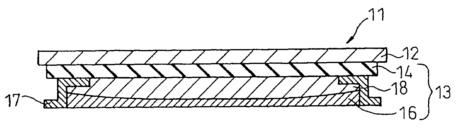
[0081]FIG. 4A is a longitudinal sectional view showing an outline of the heat plate for fixation according to the present invention. On the reverse face of the metallic base plate 12, there is provided a heating resistor 13 which is composed of a heat transmission strengthening layer 14, heating resistor layer 15 and protective layer 16. At both end portions of the heating resistor layer 15, there are provided electrode layers which are represented by reference numeral 17 in the drawing. The lead-in terminals 17 are connected to the electrode layers. The lead-in terminals 17 are connected to an electric power source not shown in the drawing.

[0082]The metallic base plate 12 is a member for conducting heat to the endless belt for fixation described later. This metallic base plate 12 is composed of an aluminum plate, nickel plate, galvanized sheet iron and the like. A reverse side of the metallic base plate 12, which comes into contact with the heating resistor 13, is fabricated to hav...

third embodiment

[0109]In this third embodiment, the heating resistor 13 has a laminar structure composed of a heat transmission strengthening layer 14, temperature control type heating resistor layer 19, heat transmission strengthening layer 20, heating resistor layer 15, heat insulation strengthening layer 21, heat reflecting layer 22 and protective layer 16 which are laminated. In the production of this heating resistor 13, the screen printing method can be most appropriately applied.

[0110]Especially, it is preferable that the temperature control type heating resistor layer 19 is made of resistor material, the temperature coefficient of which is positive. Concerning the resistor material, the temperature coefficient of which is positive, it is possible to use the primary resistor materials described before, and also it is possible to use a single metal such as Ge, Si or Zn or SnZn alloy or Y3FeO12 as auxiliary materials. Depending upon the characteristic of the positive temperature coefficient, w...

fourth embodiment

[0116]As shown in the drawing, in the fourth embodiment, the sections of the heating resistor layer 18 and the temperature control type heating resistor layer 23 are composed in such a manner that the layer thickness of the central portion is larger than that of the lead-in terminal portion. Due to the foregoing, the temperature distribution of the heating member can be maintained uniform.

[0117]Since the temperature coefficient of the temperature control type heating resistor layer 23 is negative, when the temperature of the heating resistor layer 18 is locally raised, the resistance is lowered and the heating electric power is reduced, so that the temperature of the heating resistor layer 18 is moved to a lower side. In contrast, when the temperature of the heating resistor layer 18 is decreased locally, the resistance is increased and the heating electric power is raised, so that the temperature of the heating resistor layer 18 is moved to a higher side. That is, the temperature c...


PUM


Abstract

A heat plate for fixation comprising: a metallic base plate; and a heating resistor arranged on a reverse face of the metallic base plate, the heating resistor being formed by laminating, at least, an electric insulating layer and heating resistor layer in this order on the metallic base plate, wherein the heat plate is capable of raising the temperature of the metallic base plate to a fixing temperature when the heating resistor layer is energized and heated. A semicircular heating member for fixation comprises the heat plate which is curved so that the metallic base plate has a convex surface, a belt type fixing device is provided with the semicircular heating member, and an electrophotographic image forming apparatus is provided with the belt type fixing device comprising the semicircular heating member.

Description

RELATED APPLICATION[0001]This application is a divisional of U.S. patent application Ser. No. 10 / 106,844 filed on Mar. 27, 2002 now U.S. Pat. No. 6,826,382, which is hereby incorporated by reference in its entirety.BACKGROUND OF THE INVENTION[0002]1. Field of the Invention[0003]The present invention relates to a fixing technology, more particularly, a heat plate and semicircular heating or heat-generating element which are effectively used for fixing a toner image. Also, the present invention relates to a belt type fixing device. Especially, the present invention relates to a heat plate for fixation having high reliability and durability and capable of increasing a temperature at a high rate, used for fixing a toner image in an image forming apparatus such as a copier, printer and so forth, which is based on an electrophotographic system; a heat plate for fixing a toner image having a temperature control property, the heat plate being of a temperature control type by which an upper ...

Claims


Application Information

Patent Timeline
Patent Type & Authority Patents(United States)
IPC IPC(8): H05B1/00G03G15/20H05B3/00H05B3/10H05B3/14H05B3/20H05B3/26
CPCG03G15/2053H05B1/0241G03G15/2039H05B3/262H05B3/0095
Inventor SANPEI, KOICHIMORI, MITSUHIROYANO, AKIOKIMURA, MASATOSHIKONISHI, MASAOKAWAMURA, TAKAOHARADA, AKIONISHI, TSUYOSHIYAMAMOTO, YUKIOOHBAYASHI, YOSHIAKITAKEHARA, NAOYAIMAI, TORU
Owner TAKAO KAWAMURA
Why Eureka
Try Eureka