Conformal range migration algorithm (CRMA) "KARMA"

a technology of motion compensation and automatic range migration, applied in the field of motion compensation of radar, can solve the problems of reducing its utility and becoming less accurate, and achieve the effect of improving the motion compensation of coherent combination of pulses and clearer sar images

Active Publication Date: 2006-01-17
RAYTHEON CO
View PDF20 Cites 17 Cited by
  • Summary
  • Abstract
  • Description
  • Claims
  • Application Information

AI Technical Summary

Benefits of technology

[0010]Motion compensation for coherent combination of pulses is improved by a method for acquiring a synthetic aperture image of a scene on earth's surface. A great circle is centered with respect to the earth's center. The great circle has an axis perpendicular to a first plane. The axis passes through the earth's center. The first plane contains the great circle and includes the earth's center. The great circle has a first center defined by an intersection of the first plane and the axis. The scene has one or more radar scatterers and is located on a surface. The radar system is mounted on a moving platform moving with a component of motion in a direction along the great circle. The radar comprises a radar receiver for digitizing the

Problems solved by technology

Slight deviations in the accuracy of the motion compensation of incoming pulses introduces distortions over the whole SAR image, reducing its

Method used


Image

  • Conformal range migration algorithm (CRMA) "KARMA"
  • Conformal range migration algorithm (CRMA) "KARMA"
  • Conformal range migration algorithm (CRMA) "KARMA"

Examples


Embodiment Construction

[0017]The present invention describes a method for motion compensating pulses for clearer SAR images using concepts related to the Range Migration Algorithm (RMA). The structure of the RMA is based on a convolution. Generally, it consists of a two dimensional Fourier transform, then a multiply operation, a change of variables to get to rectilinear coordinates, and finally an inverse Fourier transform.

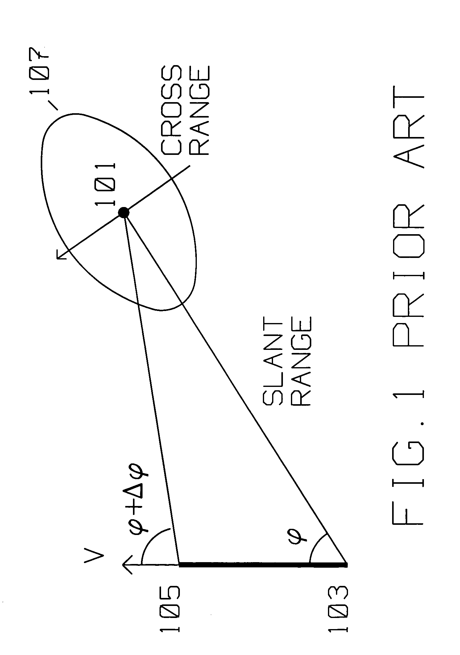
[0018]FIG. 1 shows the typical prior art geometric relationship between a moving platform carrying a radar transmitter / receiver using Synthetic Aperture (SAR) spotlight methods and target area 101 to be imaged by said radar transmitter / receiver. The moving platform is initially at position 103, travels with velocity V in the direction shown to position 105. In SAR spotlight mode, the SAR antenna is actively oriented towards scatterer 101 as the platform moves with respect to scatterer 101 with velocity V. The moving platform moves from position 103 to position 105, while adjusting the s...


PUM


Abstract

Motion compensation for coherent combination of pulses facilitates a SAR image of a scene on earth's surface. A great circle (406) is centered with respect to the earth's center, The great circle (406) has an axis (412) perpendicular to a first plane. Axis (412) passes through the earth's center. The first plane contains great circle (406) and includes the earth's center. Great circle (406) has a first center defined by an intersection of the first plane and axis (412). The scene has one or more radar scatterers and is located on a surface (402). The radar system is mounted on a moving platform (400) moving with a component of motion in a direction along great circle (406). The radar comprises a radar receiver for digitizing the radar returns having a phase from scatterers on surface (402), and a computer for focusing the phase of said radar returns from the scatterers on surface (402). The surface (402) is located on a local scene centerline circle (408), the local scene centerline circle (408) defining a second plane. This second plane is parallel to the first plane. The local scene centerline circle (408) is centered on the axis at a second center, where the second center is displaced with respect to the first center along the axis by a distance (414). The phase of the radar returns received from the scene is compensated for the motion of the moving platform (400) using a cylindrical coordinate system referenced with respect to the second center to yield a SAR image.

Description

[0001]This application is a continuation in part of U.S. patent and Trademark Office application Ser. No. 10 / 967,959, filed Oct. 19, 2004, titled Mensuration for the Conformal Range Migration Algorithm (PD 03W139), and application Ser. No. 10 / 911,438, filed Aug. 4, 2004, titled Motion Compensation for Convolutional SAR Algorithms (PD 03W137).BACKGROUND OF THE INVENTION[0002]1. Field of the Invention[0003]This invention is in the field of motion compensation of radar returns for use with Synthetic Aperture Radar imaging.[0004]2. Description of the Related Art[0005]Synthetic Aperture Radar (SAR) radar is used for ground mapping as well as target identification. The general principle behind SAR is to coherently combine the amplitude and phase information of radar returns from a plurality of sequentially transmitted pulses from a relatively small antenna on a moving platform.[0006]The plurality of returns creating a SAR image generated by the transmitted pulses along a known path of the...

Claims


Application Information

Patent Timeline
IPC IPC(8): G01S13/90
CPCG01S13/9035G01S13/9019G01S13/9088G01S13/904
Inventor HANSEN, CHARLES T.LAWRENCE, MICHAEL E.
Owner RAYTHEON CO
Why Eureka
Try Eureka