Microscope

a microscope and beam path technology, applied in the field of microscopes, can solve the problems of minor impairment of the observation beam path of the microscop

Inactive Publication Date: 2006-01-17
EURO LAB FUER MOLEKULARBIOLOGIE EMBL
View PDF15 Cites 29 Cited by
  • Summary
  • Abstract
  • Description
  • Claims
  • Application Information

AI Technical Summary

Benefits of technology

[0005]The object of this invention is to provide a microscope of the type defined in the preamble so that it causes the least possible impairment in microscopy possibilities, in particular with regard to the possible wavelengths of the illumination light and / or the observation light.

Problems solved by technology

Due to the fact that the illumination light is concentrated on at least one illumination beam, locally limited beam guidance elements may be used accordingly, which cause only minor impairment in the observation beam path of the microscope (usually outside of the optical axis).

Method used


Image

  • Microscope
  • Microscope
  • Microscope

Examples


Embodiment Construction

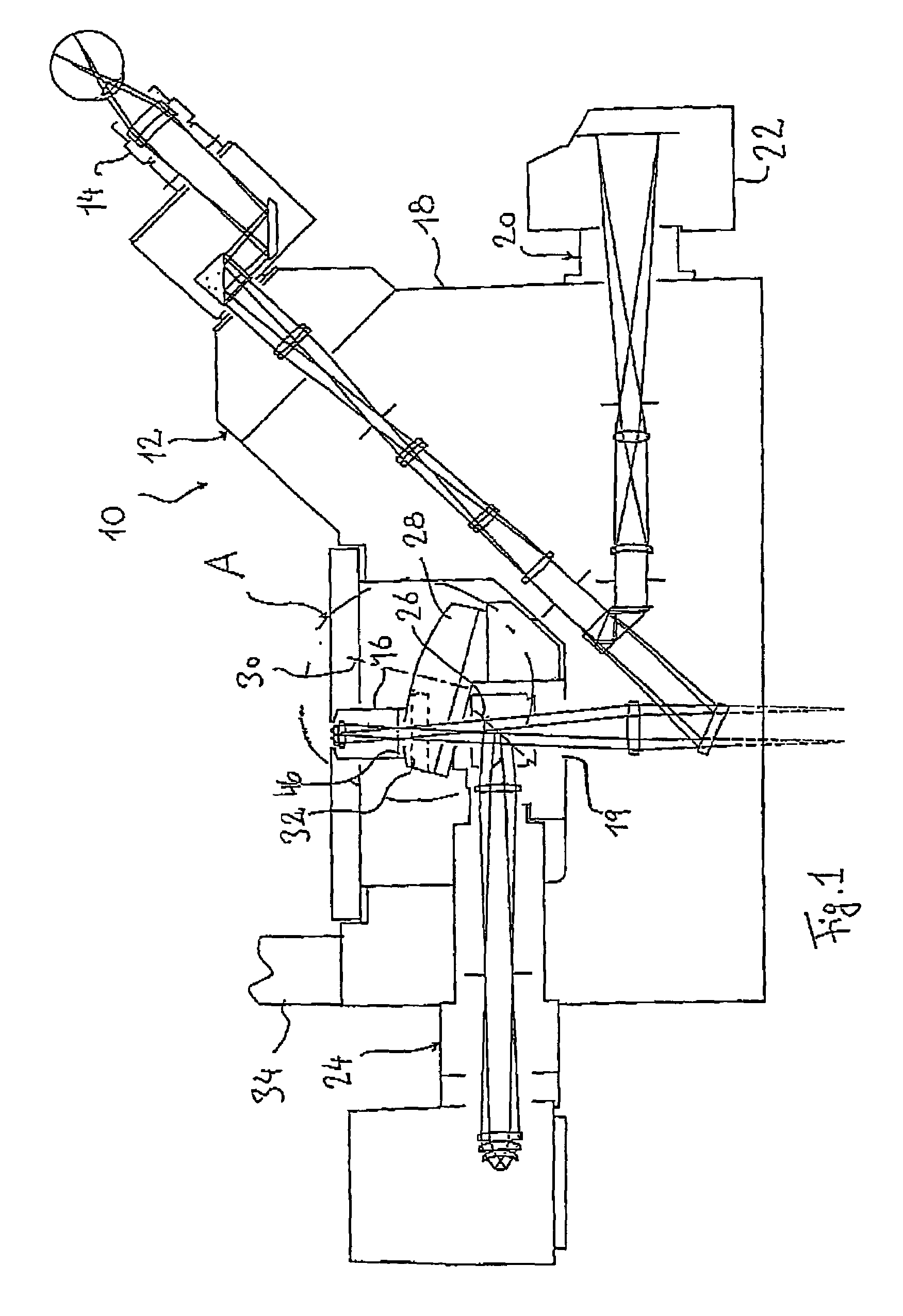
[0041]The schematic sectional drawing according to FIG. 1 shows a traditional microscope in an inverted configuration (Carl Zeiss Axiovert 100, 135, 135M, Carl Zeiss Jena). The main parts of the microscope, which is labeled as 10 in general can be seen here, namely a visual observation part 12 with an ocular 14 at one end of the beam path and an optics system (objective) 16 on the other end and a plurality of optical components inserted in between within a passage 19 of a microscope housing 18. The beam path of a photographic observation part with a camera 22, the outline of which is shown here, can be coupled into the beam path.

[0042]Furthermore, the beam path of an illumination part 24 can be coupled into the visual beam path (via a partially transparent mirror 26 beneath an optics system revolver head 28 which carries the optics system 16 with the axis of rotation 30 of the revolver).

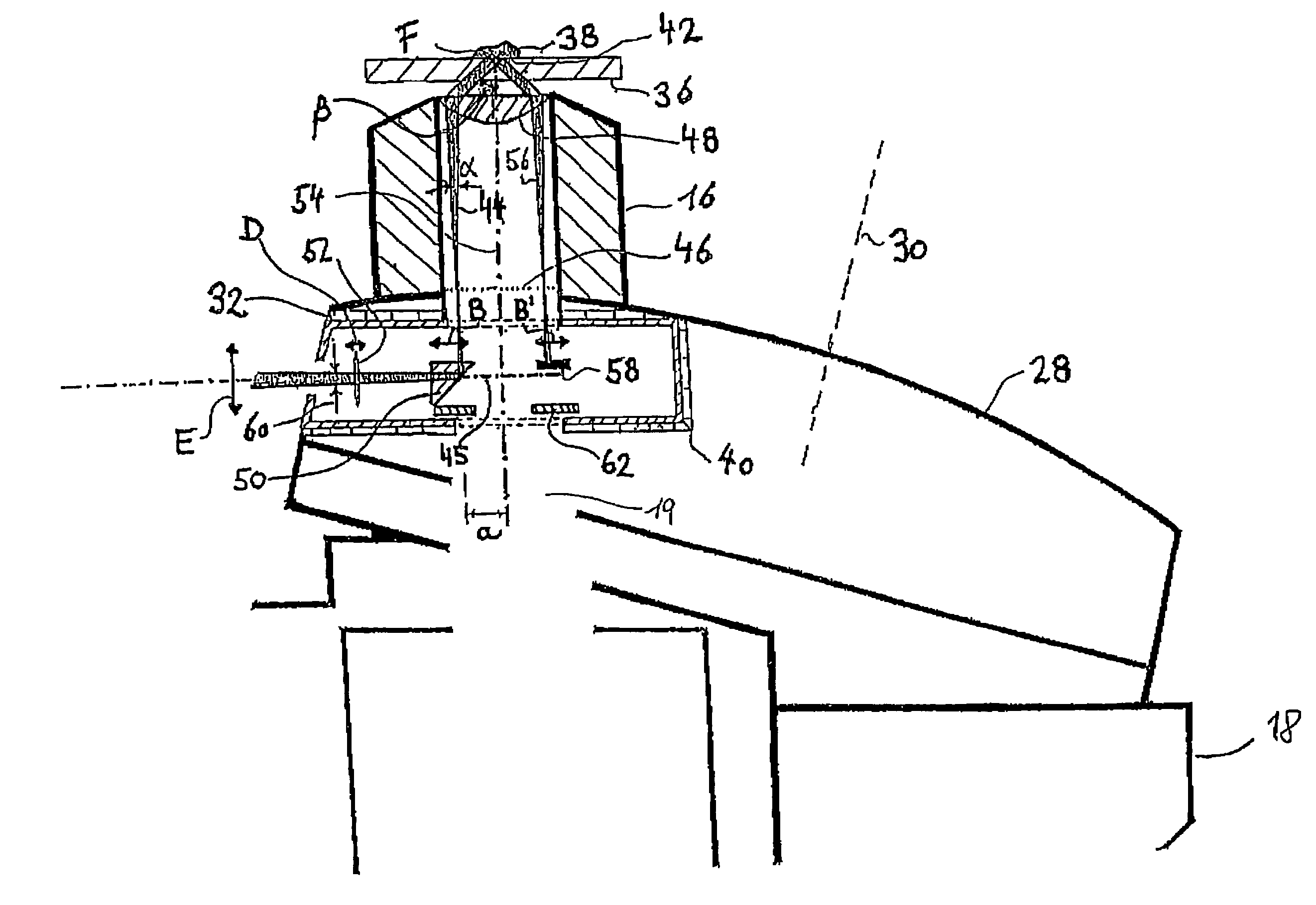
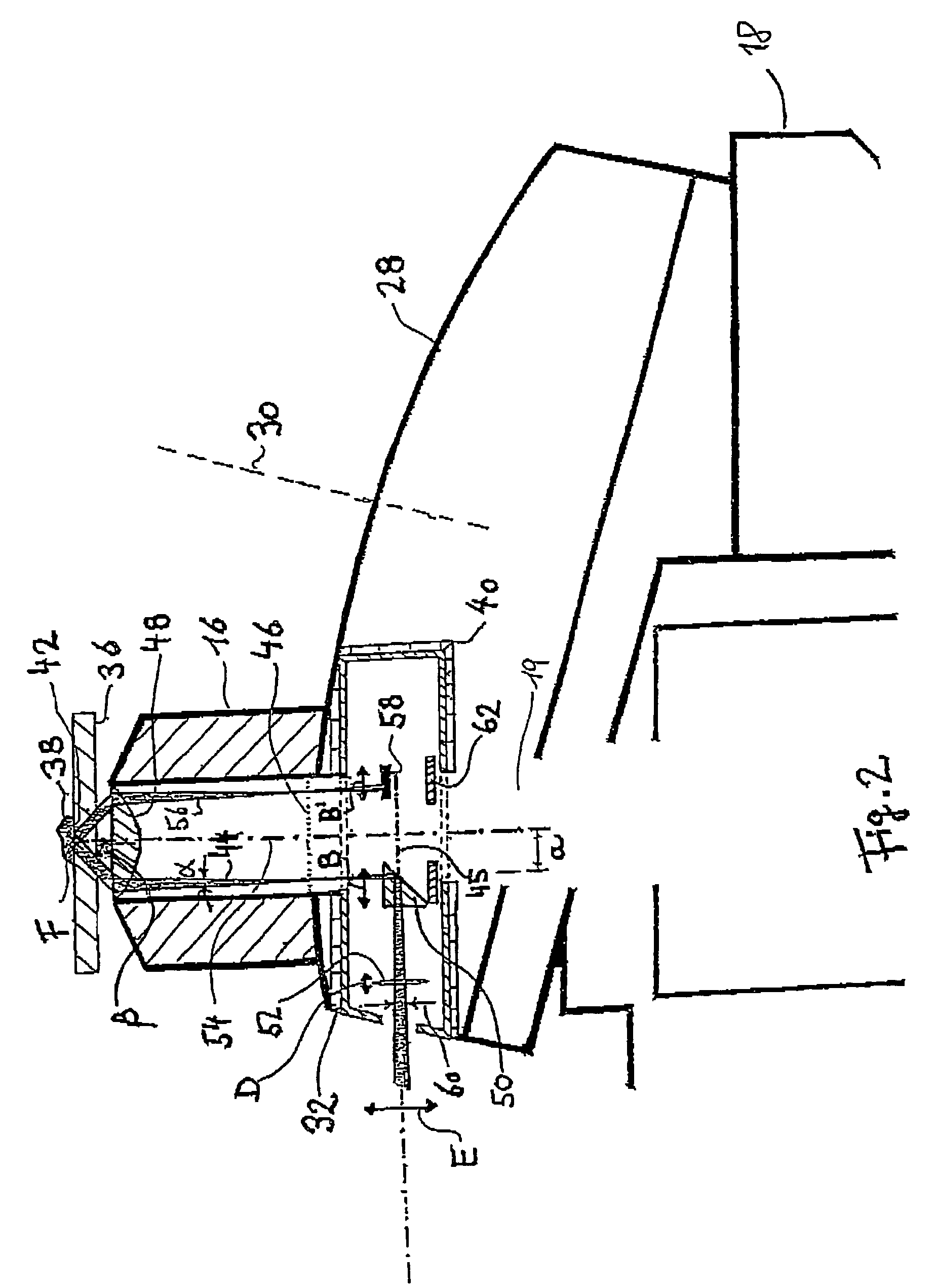
[0043]With the traditional microscope 10, an adapter receptacle 32 (indicated with dotted lines i...


PUM


Abstract

The invention relates to a microscope comprising a microscope housing (18), an optics system (16) consisting of at least one lens system that contains at least one respective lens (48) and is positioned at one end of a passage (19) of the microscope housing (18), at least one observation device, in particular an ocular, located at the other end of the passage (19), an illumination device, whose light forms at least one illumination beam (44), originating from a plane of incidence (45) that vertically intersects the passage (19), said beam traversing the lens system and striking an object carrier (36) at a predetermined angle (β). According to the invention, the illumination beam or beams (44) originating from the plane of incidence (45) is/are provided by an optical device, whose cross-section lying in the vicinity of the passage (19) is substantially smaller than the cross-section of said passage (19).

Description

CROSS REFERENCE TO RELATED APPLICATION[0001]This application is a 35 USC § 371 National Phase Entry Application from PCT / EP02 / 09901, filed Sep. 4, 2002, and designating the U.S.BACKGROUND OF THE INVENTION[0002]This invention relates to a microscope. More particularly, this invention relates to a microscope which includes a housing, an optics system having at least one lens system which includes at least one lens, at least one observation device and an illumination device producing at least one illumination beam that strikes a microscope slide at a predetermined angle.[0003]Such a microscope is known (Biochemical and Biophysical Research Communications, 235, 47–53). It is used primarily for the microscopy technique known by the acronym TIRM (=total internal reflection microscopy). In this technique, the illumination beam is totally reflected at an interface formed between the microscope slide and the object (the refractive index of the microscope slide is greater than the refractive ...

Claims


Application Information

Patent Timeline
Patent Type & Authority Patents(United States)
IPC IPC(8): G02B21/06G02B21/00G02B21/02
CPCG02B21/02G02B21/06G02B27/56G02B21/365G02B21/10
Inventor TISCHER, CHRISTIANFLORIN, ERNST-LUDWIG
Owner EURO LAB FUER MOLEKULARBIOLOGIE EMBL
Why Eureka
Try Eureka